Scratch Built 1:12 Ferrari 156 Sharknose 1961
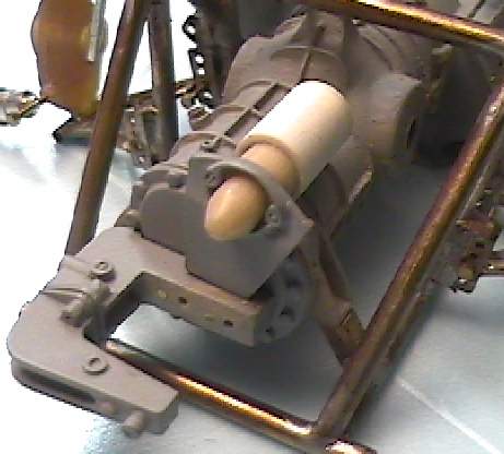
Here is the item in the location it will eventually go.
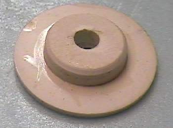
Here is my first attempt at making a disc brake. I tool a chunk of resin and tried to turn it to the desired dimensions. The material proved too soft and no matter what speed I tried to turn the thing I would get scoring or turning marks in the resin. This looked messy and out of scale. I will have to try this in aluminum.
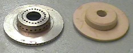
Now here is the finished disc brake in aluminum. Needless to say this took a long time to finish. There are quite a few holes around the disc. I had to pour through the little references I had t try and determine how many holes there were around the disc. I even resorted to drawing lines in my photocopies to work out how many holes there would be around the thing. Once that was done I had to figure out the distance between holes. Here is where a dial caliper is very helpful. I also tried to draw the thing up in AutoCad and then print it out as a guide. This was somewhat successful. I tried to use my Dremel tool with drill stand with a small bit for drilling. It turned out that the drill stand has a very slight play in it. No problem for most applications but errors would be obvious in this scale. I had to go twice as slow as I wanted during drilling as any pressure would cause the drill bit to wander slightly. Not a fun exercise and I do not want to do this three more times.
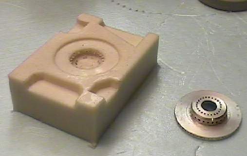
Here is the mould for the aluminum master disc. The odd shapes in the mould are keys used for a 2 part mould. I was going to do a 2 part mould but I may stick with a 1 part and then turn the excess material on the inside. Once reason for this is that I pulled the master out of the mould and I couldn't get it back in due to all the holes.
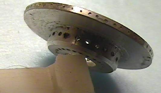
Here is the edge of the disc showing all the holes I had to drill all the way around.
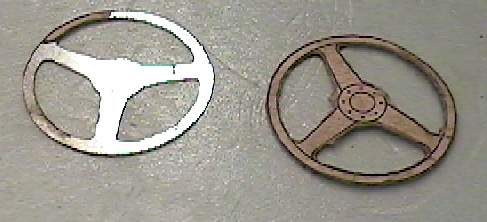
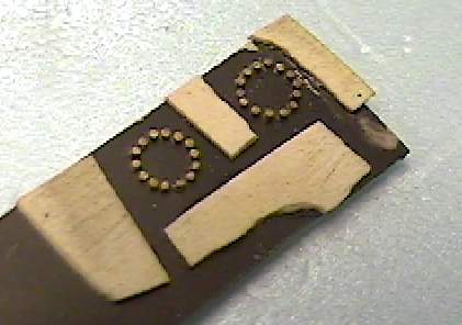
Here are 2 examples of the steering wheel I am working on. I drew up the wheel in AutoCAD and then printed it out to scale. I then super-glued this to tin sheet. I found this tin sheet to be thinner and stronger than aluminum sheet. I then took my Dremel tool with cut off wheel to cut out as much as I could following the template. Every so often the heat from the Dremelling would cause the paper template to fall off. I would just glue it back on. For the finer stuff I had a small grinding bit that I used. The next step will be the middle hub and then the wooden rim.
As you can tell I use a CAD program lot for this project. There are plenty of cheap programs that can do the same thing and can greatly increase the accuracy of your model building.
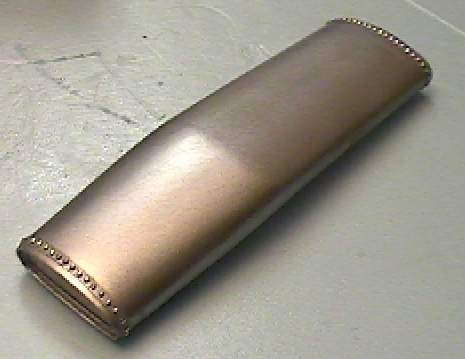
Here is the gas tank again but now with a lot of rivets. Getting these rivets is a story. I looked high and low for a suitable rivet. Photo etched rivets are flat. These rivets have a domes shape to them. I looked at Grant line bolts. I didn't see the ones I wanted and the cost to place the rivets all over the gas tanks would have been expensive if I found one the size I wanted. I looked at pin heads which would have been perfect if I found one the size I wanted. What I finally did was used my waldron punch. Now if I used as directed would have made flat discs. However the other end of my punch was cone shaped. When I reversed the punch and used it this way I would get a cone shaped disc. Doing this with aluminum sheet and they kept their shape rather nicely.
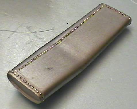
The back side showing a lot of rivets. Unfortunately the left and right gas tanks are different due to the rivets so I will have to make separate moulds.
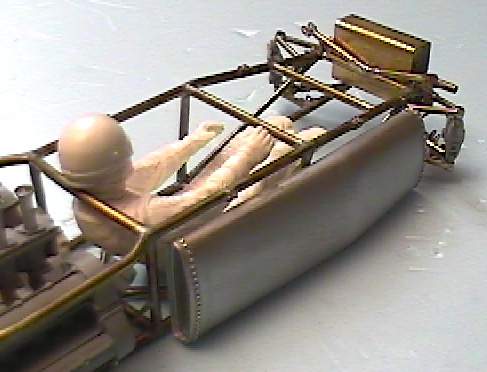
This is where the gas tanks will go.
You saw these before but here they are again. They will form part of the gas tank where the gas is poured in.