Scratch Built 1:12 Ferrari 156 Sharknose 1961
Last Revised May 24 2003
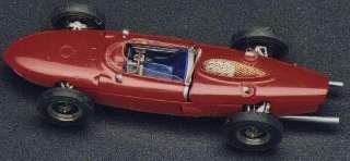
Above is a picture of the car I am trying to build. The above model is a 1:43 SRC model.
I have revamped this site to introduce pages and thumbnails. Hopefully this will make downloading of the pages quicker for people like me still on phone lines.
This project has taken a lot longer then I wanted due to a bit of burnout. Other projects also do not help. I am slowly getting back on track.
December 20th 1996
References
Not much out there. Information was gathered mostly from various books, pictures etc. Drawing mostly inaccurate
Frame
References and information on the dimensions very hard to find. Due to limited time I had to finish up the drawings for the frame. All frame drawings done on AutoCad. A styrene frame is being constructed and this will be used to check with available pictures to ensure all angles look correct. It should be noted that cutaway drawings are inaccurate and missing some tubing.
I don't think the styrene frame will be strong enough and may have to go to a brass frame. My soldering isn't the greatest so this may be an exercise in frustration.
Other Info
Body will probably be vac-formed. Thought about a brass body as outlined in Wyngroves book but this method appears labour intensive and I want to produce at least two models. My current philosophy has been to produce two super detailed models at the same time. This will allow me to try new techniques with the better looking parts going on one model and the rest going on the second. Then when I am done I can give the second model to a friend as a present or something. It may not be as refined as the one I have kept but it will still look very good.
Engine
Scratch built from styrene? Then moulds made so I can cast several. This sounds pretty heavy hence the reason the brass frame may be needed
Wheels and Tires
I have a small lathe but not one big enough to do the wheel rims. I am going to see if I can get a friend to make up a set. With these I can cast others for the other cars. Wire wheels will have to be hand laced. As for the tires I have no idea how I am going to do the treads. When I do make a sample I will probably cast these in resin. Rubber would be nice but I don't know how to do this yet
December 24th 1996
First frame almost completed and when compared to references the frame sits too low and the front section bottom frame isn't narrow enough. Also there was problems in the rear. A couple of bars were also orientated wrong but will be corrected on the second one. Took a bit of time to line up the bars for the top and bottom sections. Frame seemed pretty strong but still not sure if it will take the weight or is strong enough.
January 6th 1997
Second main frame almost done. New pictures give me a better view of the front of the frame. A few of the minor braces not put on yet. Will have to start the mounting points for the engine, suspension etc. Drawings for the engine started
Jan 16 1997
Added the final braces to frame. Drawings for engine, suspension, gas tank brackets done. Laser printed onto overhead to hopefully make into PE parts. Will start brass frame soon but will have to plan the entire process
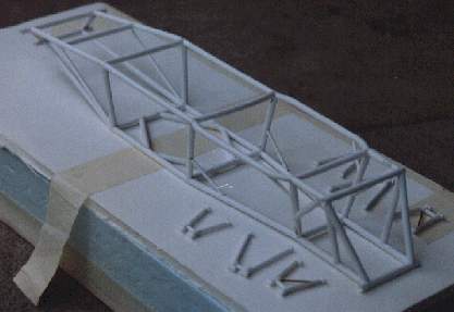
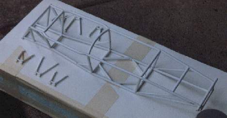
Two pictures of the frame and some suspension components
Aug 15 1997
Made some of the suspension pieces in brass. Was thinking about trying the frame in brass also but I will have to forget this since the engine is taking a bit more time than I thought.
Engine block is moving along slowly. Gearbox is the main focus at the moment. This area is getting a bit more complex and I am not sure if I can cast this item when I am done.
Oct 10 1997
Gearbox main body almost done. Getting ready to make the molds for it. Rear gearbox section is next. Too complex to make in one mold. Engine block 50% done. Test fitted the engine to frame and found that it doesn't fit. Mounting points way off. Have started a third frame
Wheels started. Rims turned. Will have to drill the holes soon to wire them. Tires still to be done
Nov 20th 1997
Just got a roll of film developed so here is the latest stuff
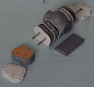
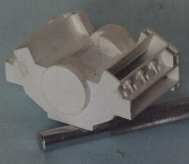
Here is the gearbox in parts. The body was carved out of Balsa-foam (the tan stuff) and then sealed with superglue and primer. The radial ribs were added by slicing the body into equal sections (as seen in the picture) and adding sheets of styrene. The longitudinal ribs were added by gluing straight lengths of strip styrene onto the surface. The front rear and bottom plates are sheet styrene with detail added. The arrow on the sheet styrene part at the back is for lining up with the rest of the gearbox.
The first attempt at the radial ribs was styrene strips bent and superglued onto the surface. This turned out to be a complete disaster and almost ruined the body. The strips would not glue down and often pulled off.
The foam stuff was easy to cut and carve into the shapes needed.. Great to work with but has to be sealed in some way before going to the next step. Due to the softness of the foam it should be used only to make a master for casting.
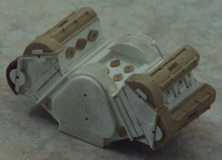
Here is the start of the engine block. Everything here is sheet styrene.
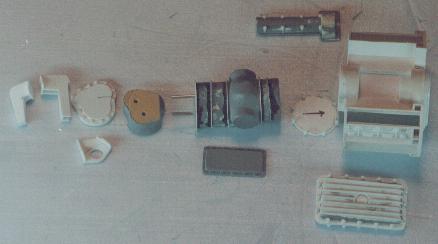
This is the relative positions of the parts when the entire assembly will be together. The items to the left will be part of the gearbox. It is these parts that make this unique from any other gearbox I have seen in kit form (the reason I couldn't copy one from another kit).
The item below the engine block is the oil pan for the engine block. The item above the engine block is the cam cover. This is the master for a mould. Four copies need to be made for the engine block.
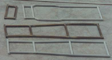
Here is the start of the third styrene frame and the brass frame. New techniques for soldering allowed me to try the brass frame.
Before I was using a propane torch or a pencil torch. The solder I used had a flux core. This involved a lot of things held together with jigs and heat sinks. A very time consuming process with a lot of errors made.
The new technique I have been using was a pencil soldering iron, flux and solder. After everything has been cut and ground to shape the parts were held together with magnets or silly putty. Flux was then added to the joint. When the soldering iron was hot enough some solder was melted onto the soldering iron. By touching the tip of the iron to the flux the solder would be sucked in. This was relatively easy and there was minimal heat transfer. If the soldering gun tip was in contact with the brass rod too long there is a danger of too much heat transfer and other joints may pull apart. I have soldered parts with an existing joint 1/8" away. After soldering some cleanup was required. (see also the tips section)
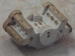
Here is the engine block almost ready for moulding. The camcovers have been cast (tan colour) and PE Ferrari logos have been added. The PE logos came from a 1:43 scale aftermarket sheet. Turns out that the PE part was the perfect size. Sometimes you do get lucky.
You will also notice tan coloured flanged items. One master was made of different sizes and a mould made. These were then cast and the copies placed where needed on the engine block.
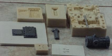
Here are the moulds and masters for the gearbox body, oil pan, gearbox end cover, cam cover and flanges. The gearbox mould has a aluminum rod running through it. I use this to position a larger aluminum rod inside the cast item. I hope to use this when assembling the wheels somehow.
When looking at the primed gearbox and cam cover I sometimes have to remind myself that I made these items from scratch.
[ Prev ] [ Next ]