Scratch Built 1:12 Ferrari 156 Sharknose 1961
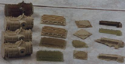
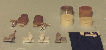
Here we have copied from all the moulds above. The light tan stuff is Alumilite. The light green stuff is Fiberglas resin. Some people have said this stuff is no good or would never cure but I have done several casting with this stuff and it have found no problems. I have done other mouldings and on a few occasions it hasn't cured. I can attribute this to not adding enough hardener or not mixing the resin enough before pouring. I have had the same thing happen with Alumilite. The resin stinks like crazy but is a lot cheaper. The other benefit of the resin is the amount of time I have to pour. Alumilite has 2-3 minute set up time. In this time I have to be able to locate and take out any air bubbles. Alumilite sets up so quick that I have to pour the gearbox in 3 sections. The resin takes anywhere from 20 minutes to an hour before hardening (depending on the amount of hardener), more than enough time to take air bubbles out. The resin is brittle while the tan Alumilite is softer. However if you mix in too much of the darker Alumilite stuff with the clear stuff you will also get brittle castings.
April 11th 1998
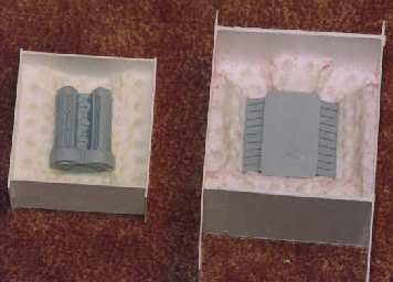
Picture of one half of the molds being made for the engine block and cylinder head. 95% of engine done. This includes the water pump, electric's, carburetors. Some molds made for these. Brass frame also mostly done. Next step is the mounting points for the suspension and suspension parts in brass.
May 20th 1998
Picture above shows the brass frame almost done. The circles show the start of the mounting points for the engine and suspension. Two brass frames were started but due to lack of time only this one will be receiving the mounting brackets.
If there was time I would be making patterns and producing photo etched brackets. Due to lack of time the brackets are all being made by hand.
ENGINE
The engine is 93% done with a few more items that have to be made and cast. A good engine is now being produced from the castings. The mounting brackets for the engine and gearbox are now on the frame. I am using 00-90 bolts to mount the engine. Various locations are drilled and tapped. Due to the size of the engine gearbox combination these parts have to be installed in the frame separately.
Have started to add PE bolt heads to the engine and gearbox
TIRES & WHEELS
Turns out the tires from the Tamiya 1:12 Lola T-70 has the correct tread pattern. The bad news is that they are not the correct width. Molds have been made for the tires and I have been casting half wheels. With these halves I have been making tires the correct width. I now will have to drill and turn the inside of the tires so the rims will fit on. Wheel hubs will have to be made before I can wire them.
June 20th 1998
SUSPENSION
I have finished the suspension arms. These have been made from brass rod and soldered together. Wasn't easy to get these buggers lines up properly. Front and rear as well as upper and lower arms are different.
SHOCKS
Front shocks have been made from turned aluminum and springs. Used a lathe at work to do this. Boy do these look neat.
GAS TANKS
Started these. Am going to have to make two of them. They are large and will take a lot of RTV material. Sigh... Boy is this taking longer than I thought.
Aug 24 1998
Haven't had an update in a long time so there will be quite a few items I will be adding.
LATHE
Just got a Sherline lathe. Now I can turn stuff at home (Yess!!)
SUSPENSION MOUNTING POINTS
With all the suspension arms I then had to make the mounting points on the chassis. These mounting points were drawn out on a computer. I next tried to make photo etched items with a method I learned from a fellow model club member. I figure with this method I can have mounting points that are the same. Unfortunately this was only partially successful so I basically had to scratchbuilt most of the suspension parts by hand.
Soldering all the suspension mounting points was hell (or close to it). Due to the very slight differences in the suspension arms every mounting brackets was custom fit to the model.
SHOCKS
To show how silly I am, I have been using X-acto knife handles as stock for turning aluminum. I got a bunch on sale at a local hobby shop and they do turn very nicely. I have now found a local supplier of aluminum rod with different diameters and a lot better prices.
UPRIGHTS (wheel hubs)
I have just finished casting the front and rear uprights. Of course they are all different so I had to make four different masters out of Balsafoam and styrene. Took a bit of time making the moulds for these items mainly because I have been lazy. Once these were done I cast them out of Alumilite.
GASTANKS
The gastanks are on both sides of the car. Both gastanks are slightly different so a master will have to be made of each. The main difference is the filler cap/ fuel line on top of the tank.
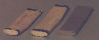
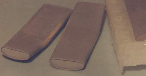
I started with the basic shape of the gas tank. I then made a silicone chalking mould of this. This isn't as detailed as RTV rubber but a lot cheaper. I tried making this mould with Vinamold but this turned out to be a complete mess and slightly damaged my master :(.
I then cast two copies to work with. These were cleaned up and filed to the correct shaped. The construction of the real gastanks has the ends riveted on. This produces a lip that was recreated with thin sheet styrene wrapped around and sanded to the desired depth. Holes were then drilled around this lip to prepare it for rivets.
CLUTCH
The clutch still has to be done
October 20th 1998
ENGINE
Just saw a friends 1961 Autocourse and of course there is one picture of the engine that I have never seen before. There are slight differences from my engine block. Won't change my current model but will change the next one I do.
CLUTCH
This part has taken me quite a bit of time to do. With holes everywhere I almost went bonkers drilling the thing out. The bottom section with the gear teeth was also a stumbling block. After much searching I found a little music box with the correct (or close) diameter gear teeth that I needed. This parts is almost ready to finish and cast but this may be the hardest item I will be casting due to the holes. Can be very hard to try and mold this to get all the holes in the master.
WHEELS
Had a friend turn the rims for me out of aluminum. The next step was to drill all the holes around the rim. Of course I didn't want to do this the sandwich method but the way they appear on the rear cars. I guess I deserve the punishment but drilling the holes around the rim took forever. Had to make sure they were evenly spaced and drilling through the aluminum killed my hand.
I am wiring the wheels now. This is another time consuming task as the front and rear wheels have different patterns. Tried wiring it with wire but this turned out a mess. Am now doing it with hardened steel. Looks ok so far but trying to cut this stuff has ruined one of my nippy cutters. This better work out because I am in no mood to take it apart and start again. Am using 0.015" wire. 0.010" wire looked too thin but now after looking at pictures it does look correct. (Damn)
Doesn't look like much progress but my excuse is that I am working on others box stock kits.
November 7th 1998
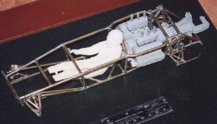
Here is a picture of the frame wit the engine in it. The driver is from the Tamiya 1:12 Lotus 49 kit to give a relative size to the model. The engine has to fit into the chassis piece by piece. The block goes in first from the top, the gearbox goes in from behind and the final step (so far) is the carburetors. I will still have to work on the cooling hoses and exhaust. The "C" shape space in the back is for the outboard clutch I am working on.
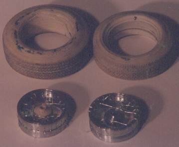
The top two items are the front and rear wheels I have cast. They still need cleaning up. The two items in front are my first two failed attempts at wiring the wheels. I will have to try a third method. I tried to get some thin wire and thread the wire all around to wire the wheels. Excellent theory if the wire was flexible. However the wire is not flexible and kinks developed that I could not get out. I also felt that the wire I was using was too thin.
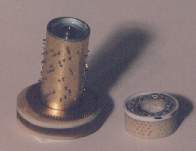
This is what I am going through to produce the clutch. The item on the right is the main body with a billion holes drilled into it. At this moment I am not sure how I am going to cast this and make sure the RTV rubber gets into all the holes. The item on the left is part of a music box that I took apart for the toothed gear at the bottom. This is needed for the bottom of the clutch.
Feb 13 1999
Well the wheels are finally wired up. It took three tries with three different methods but they are done. The tires have been painted and all the little errors fixed. The next step is the gas tanks. Yes I know I said this before but now I mean it. I have made the brackets for the gas tank and have soldered these onto the chassis. I will have to learn how to properly solder since what I am doing is still a mess. It doesn't help that I solder occasionally.
Project has been moving slowly. Hopefully after the gas tanks are done and I move to another part of the car the enthusiasm will pick up.
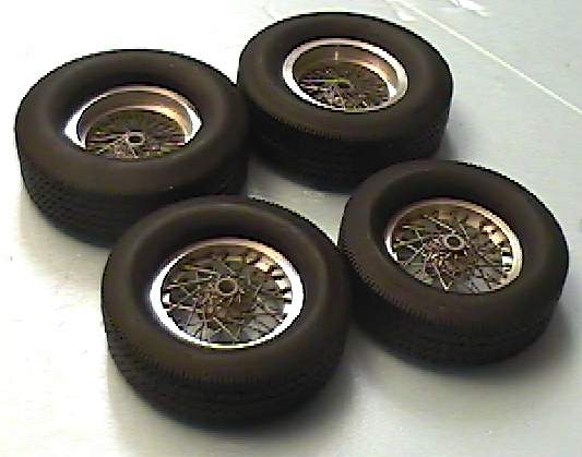
Here are the wheels and tires finished. See next page for details