|
8001.JPG
|
|
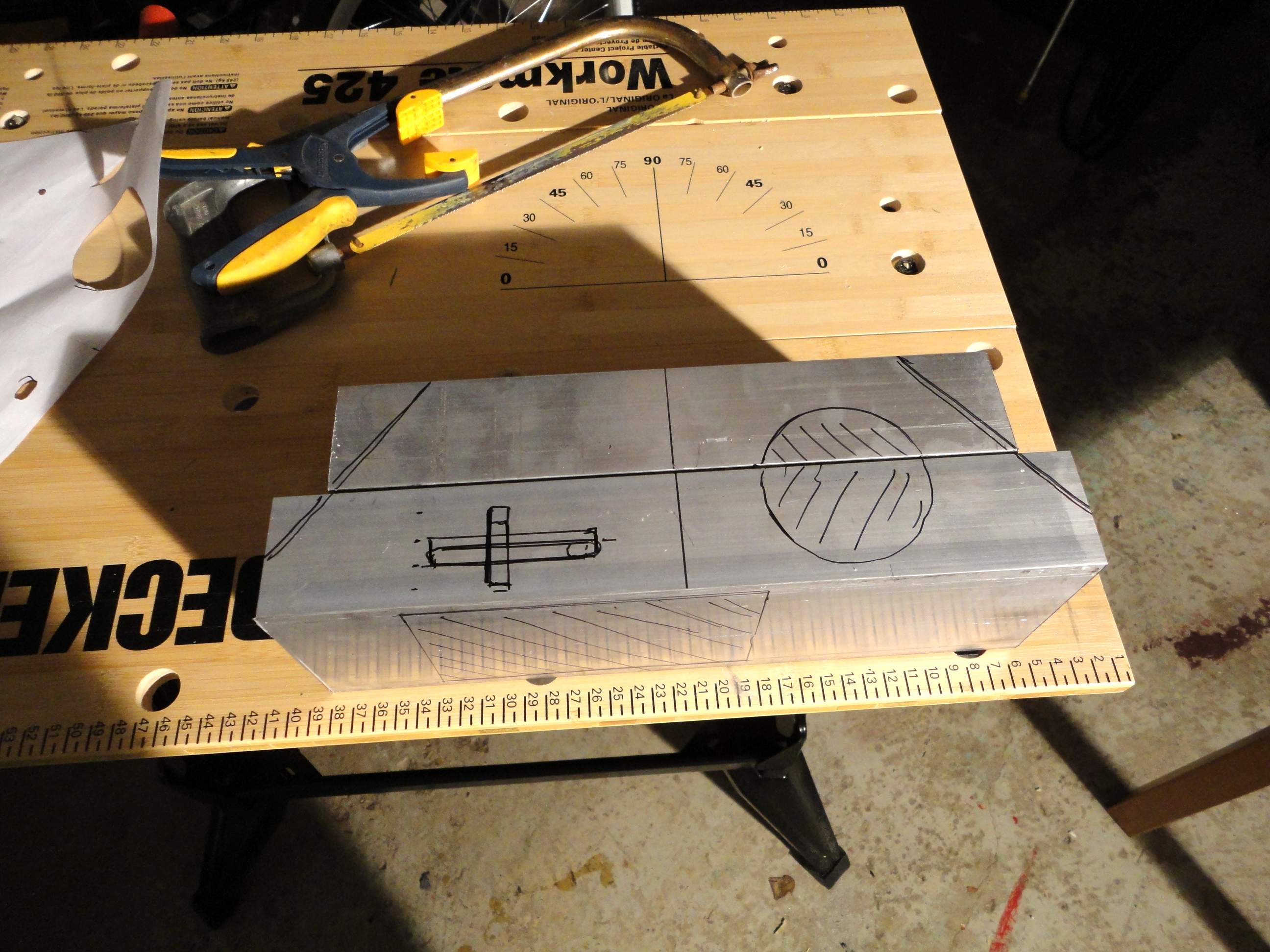
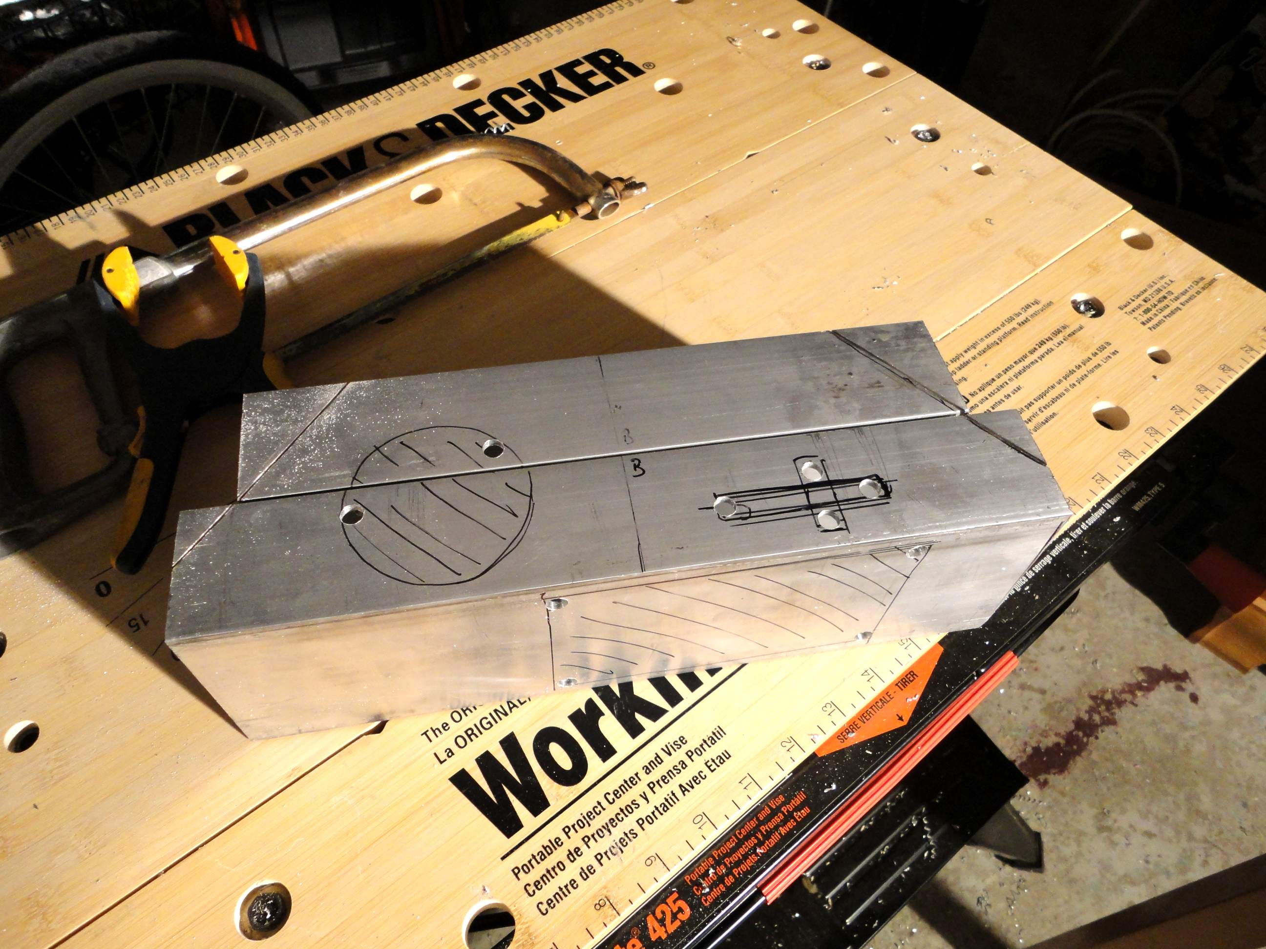
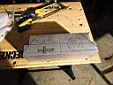
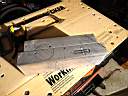
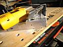
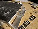
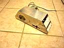
Here is the aluminum tubings
marked out with a marker to show where I want to cut. The cross location will depend on
your belt length and the diameter of your wheel. Older scooters had 4in wheels while
newer ones had 5in wheels. My
designs have always pushed the wheel as far back of the foot shell as
possible for stability. A
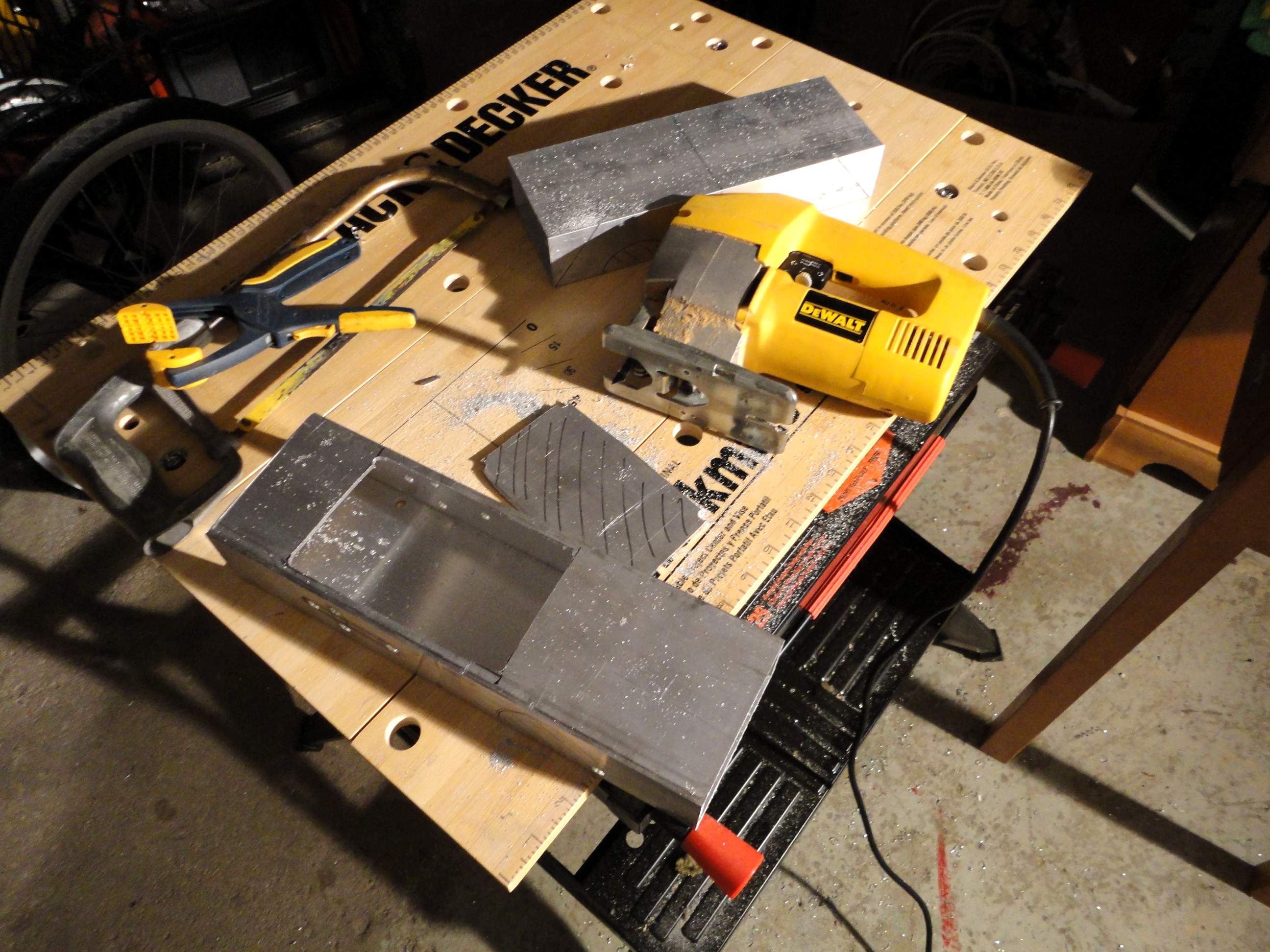
jigsaw was used to cut the length of 2x4 to the shorter lengths needed.
|
|
8002.JPG
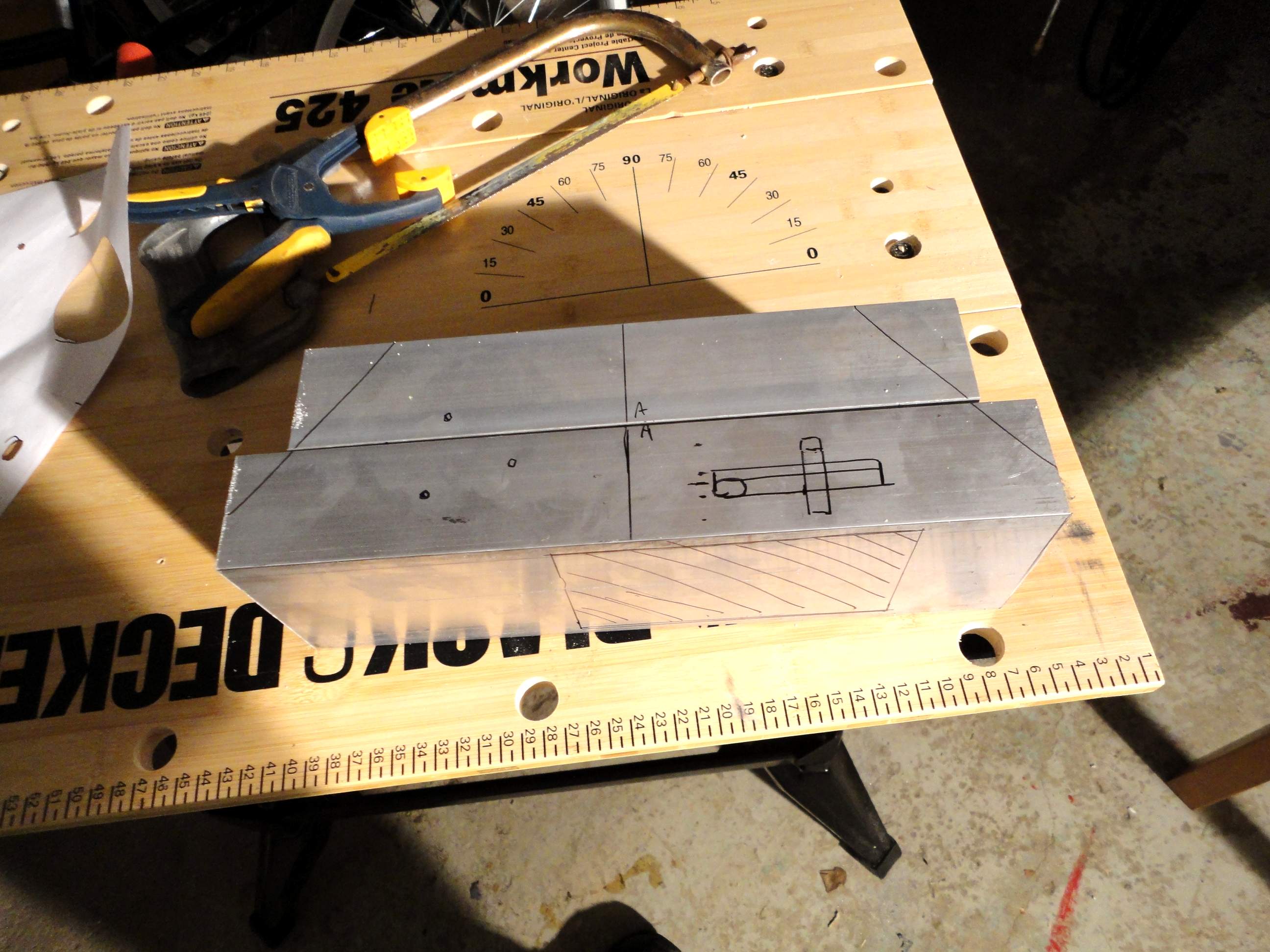
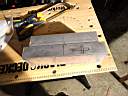
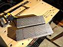
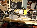
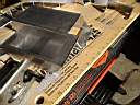
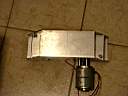
Here is the other side of the tubings. Note the location of the 3 holes for
the scooter motor as the belt or chain will have to miss the motor mount. As
you will see later.
|
|
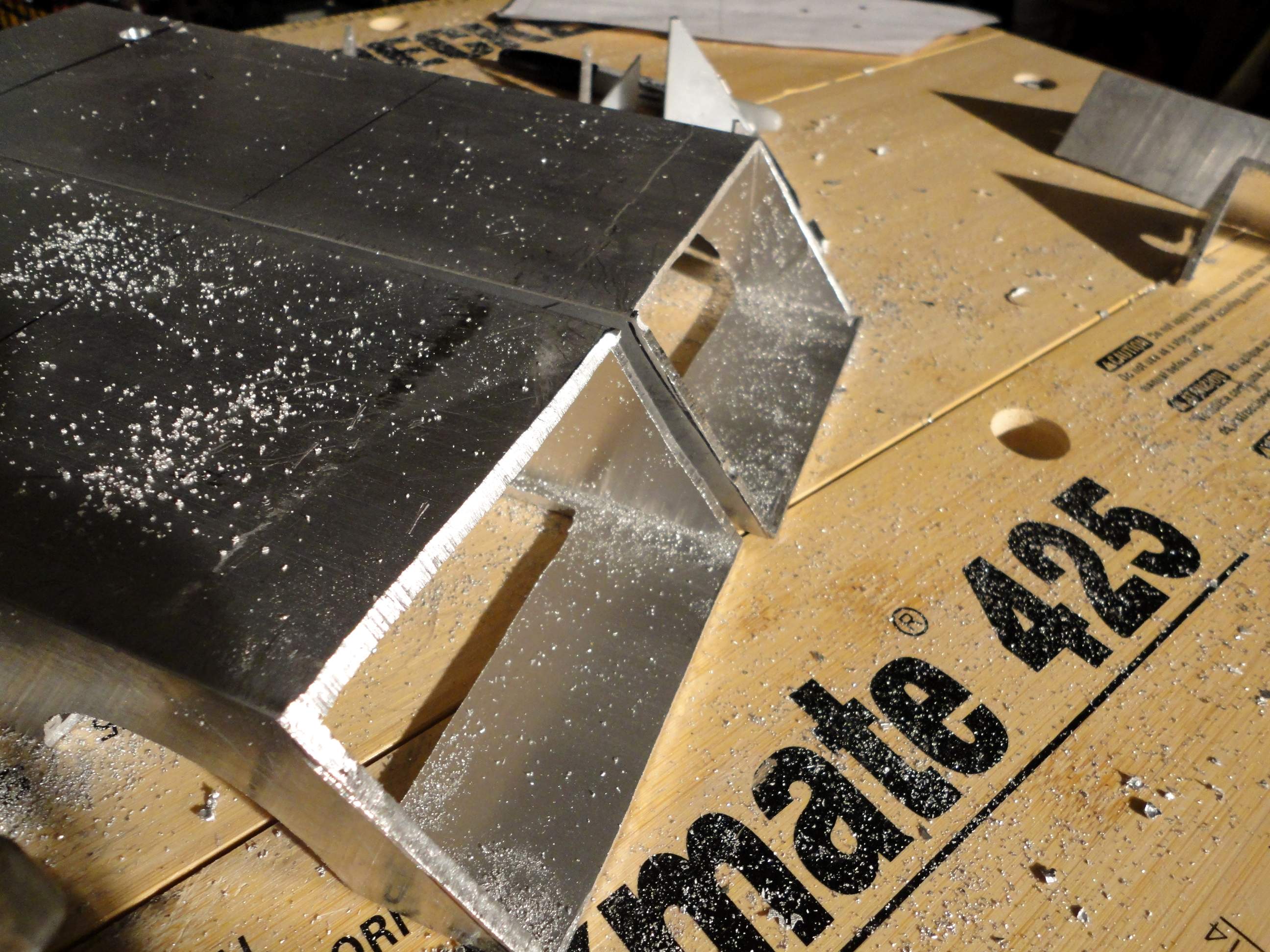
8003.JPG
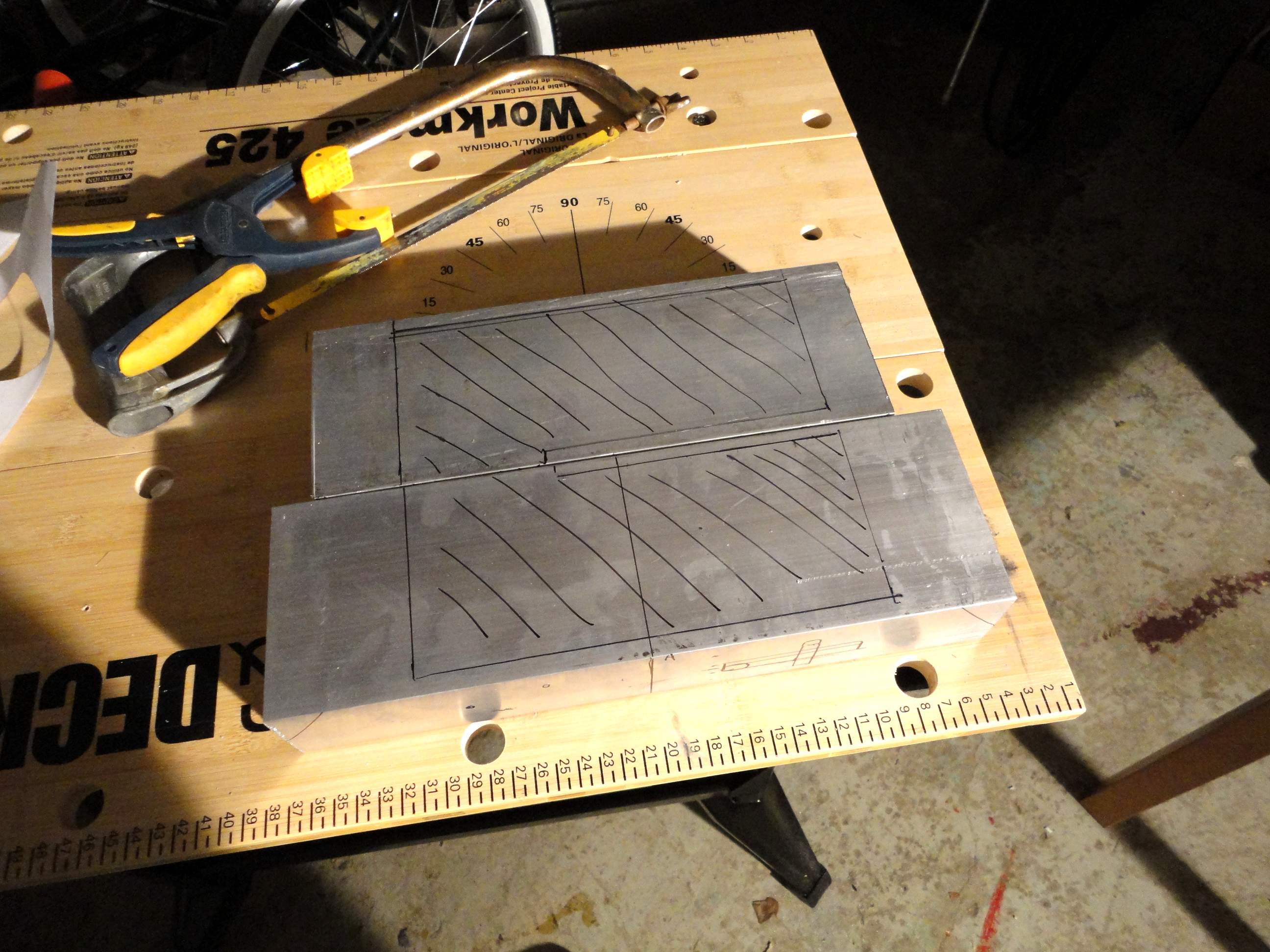
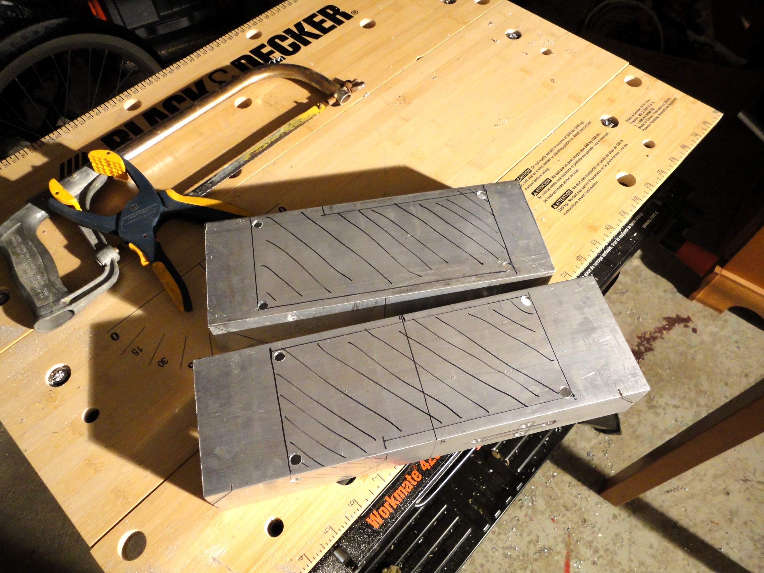
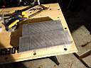
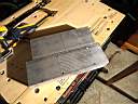
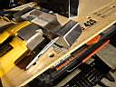
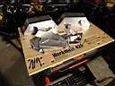
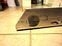
The inside of the 2x4 that will have to be cut out to
allow clearance for the wheel, motor and belt
|
|
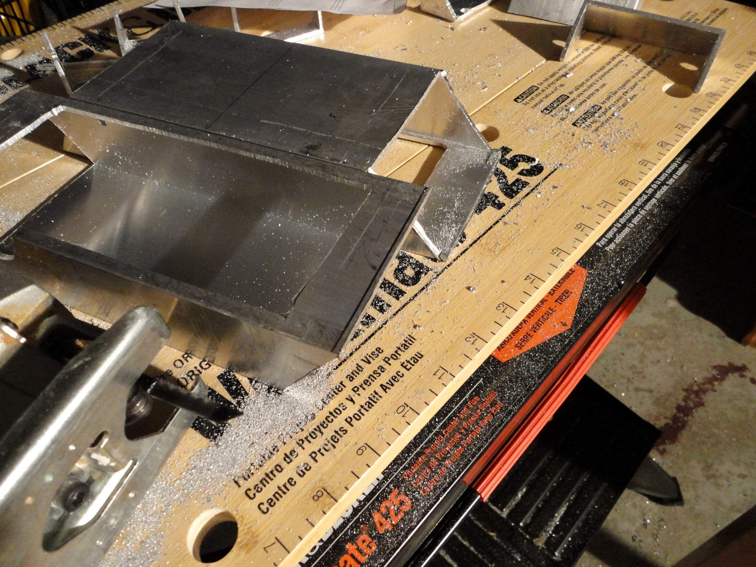
8004.JPG
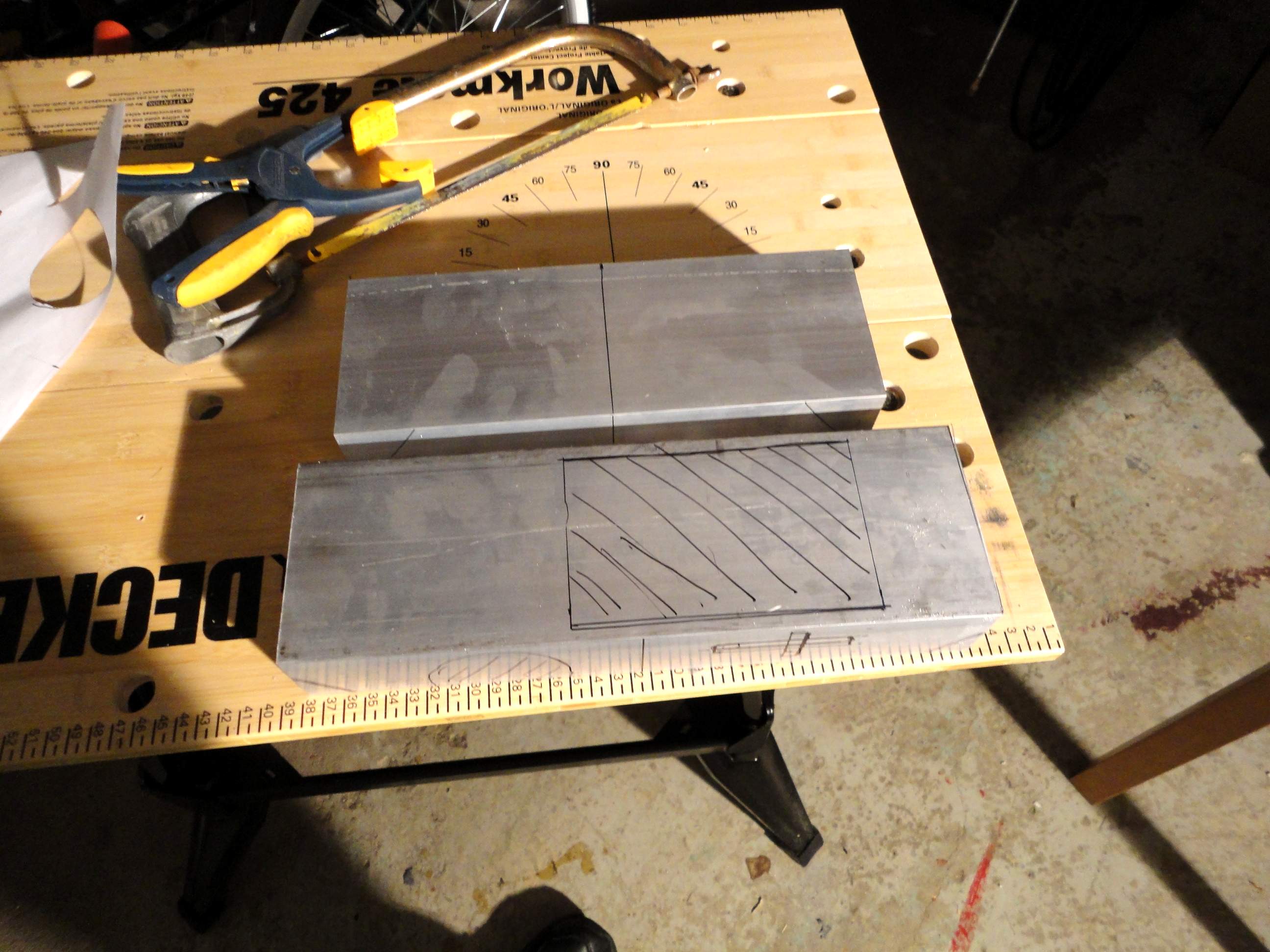
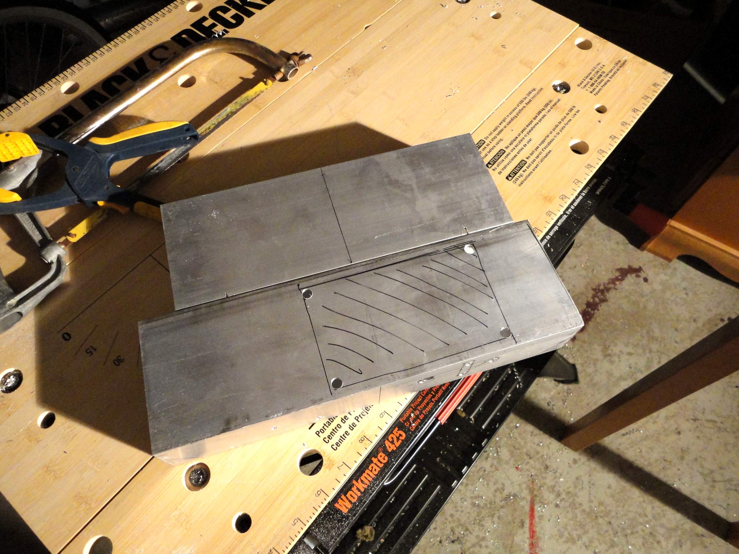
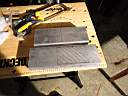
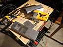
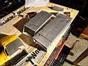
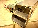
The top and bottom of the 2x4. The top has nothing at the moment while
the bottom has the hole for the wheel and belt.
|
|
8005.JPG
I drill holes to prepare for the jigsaw.
|
|
8006.JPG
More holes drilled
|
|
8007.JPG
And the final holes drilled.
|
|
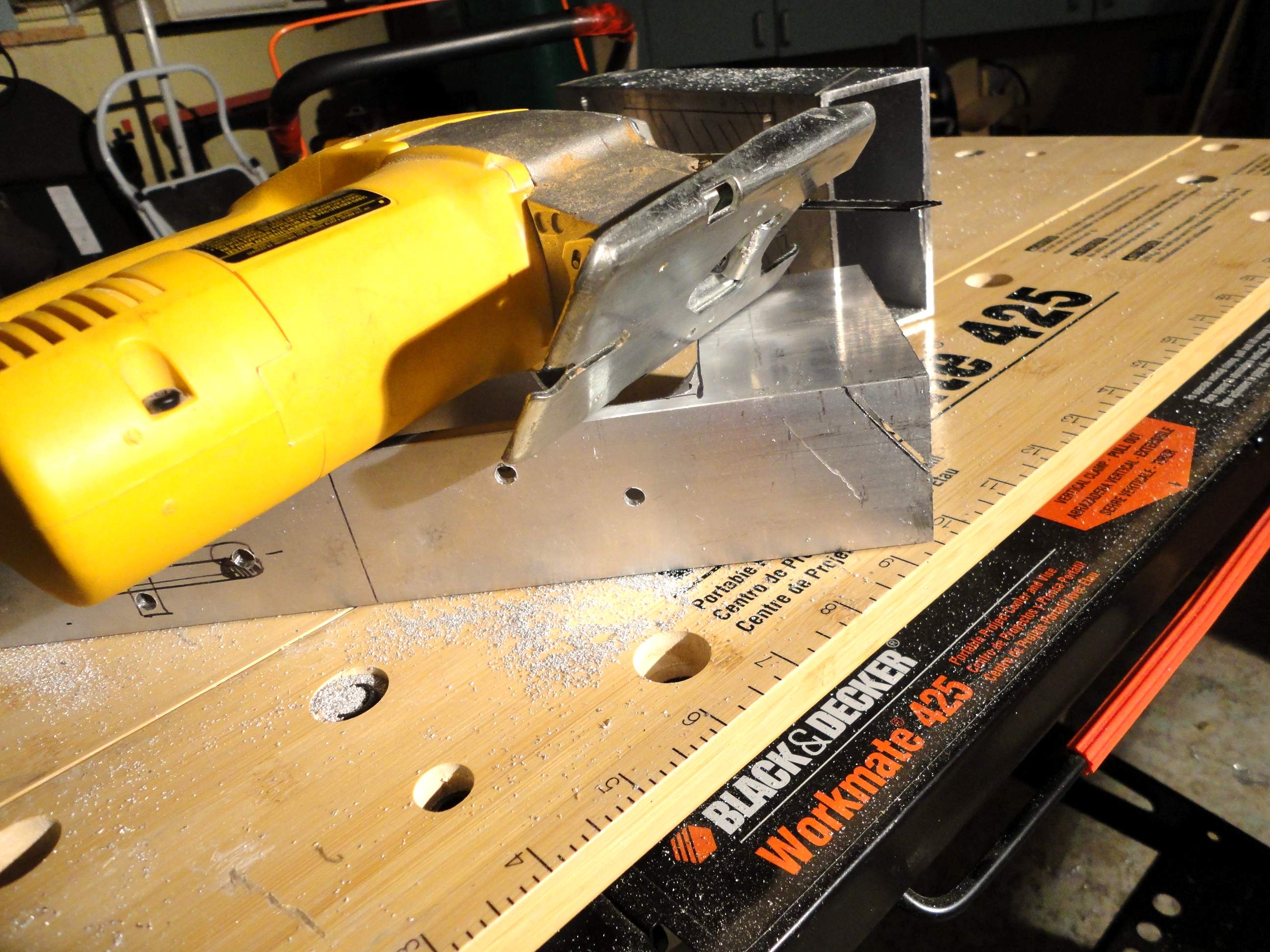
8008.JPG
The jigsaw takes time but it does work. If it feels like you are applying a
lot of force to get the jigsaw to cut through the aluminum I will put in a
new blade.
|
|
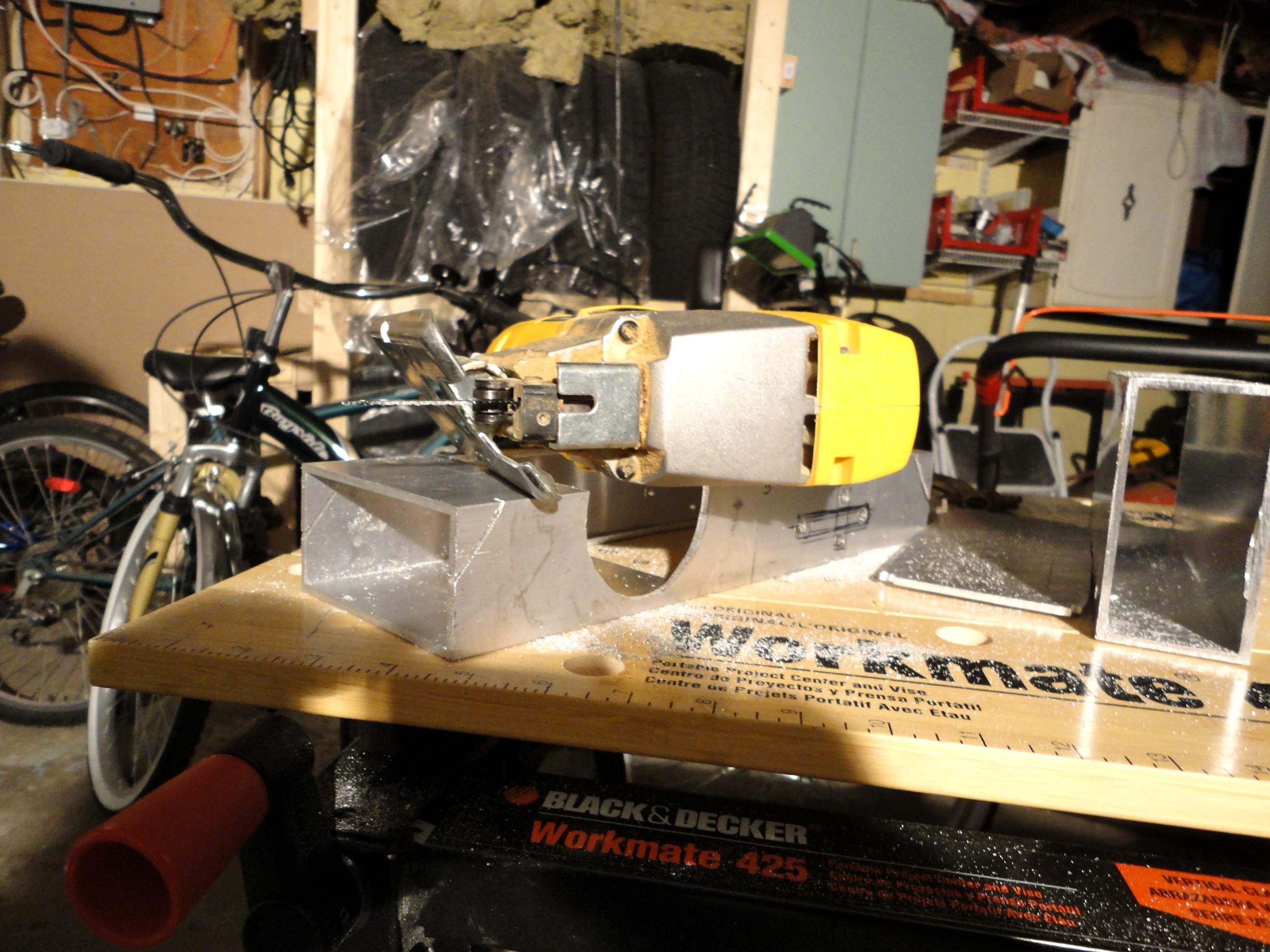
8009.JPG
I tried to get fancy and angle the jigsaw to get the end
pieces angles. This added some
time to the cutting process and was not really needed.
|
|
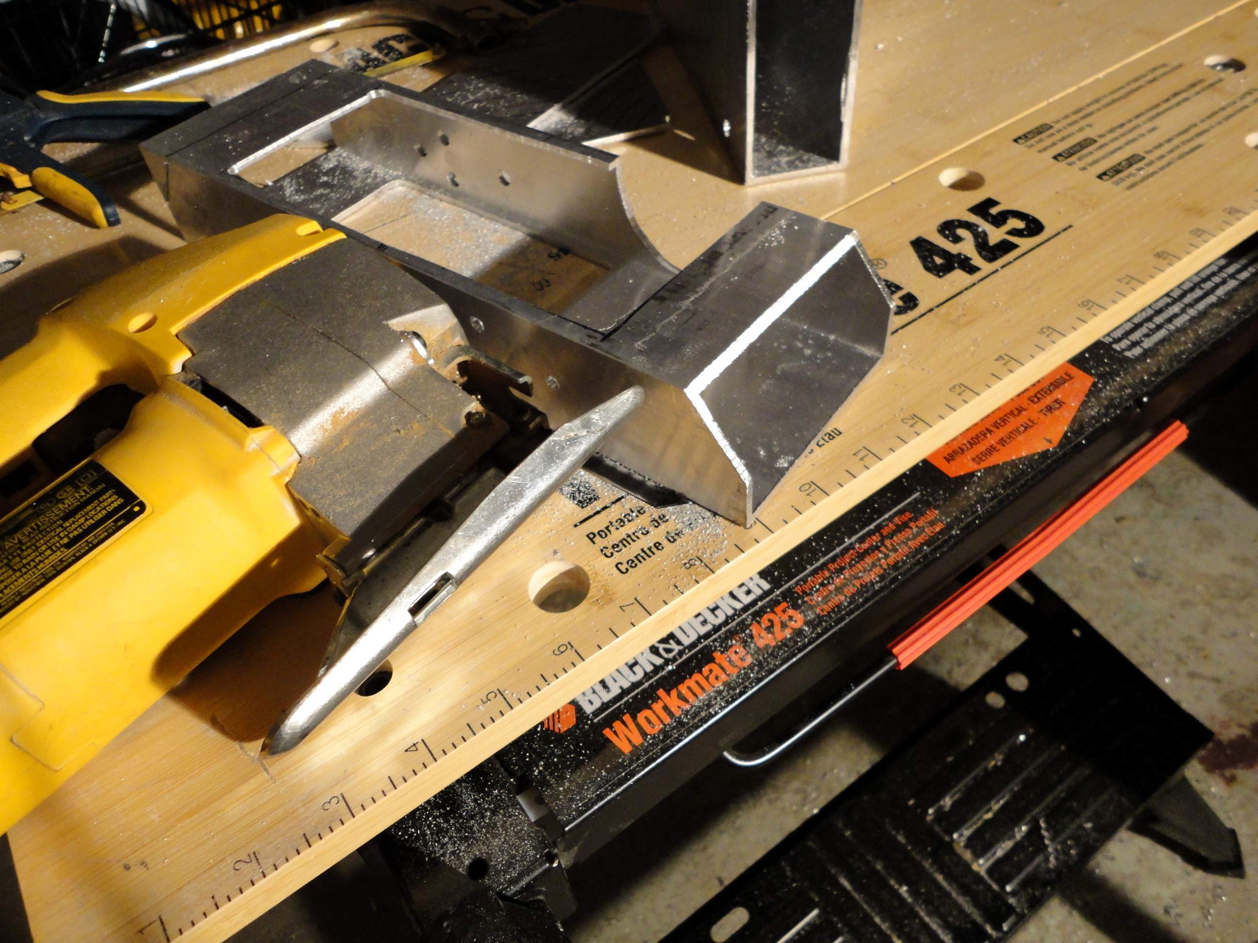
8010.JPG
It did look pretty when I finally got the angled cutting
to but in hindsight not worth it.
|
|
8011.JPG
Ooooo pretty.
|
|
8012.JPG
It took me about 3 hours to do all the cutting with
short breaks in there to rest the hand from the vibrations.
|
|
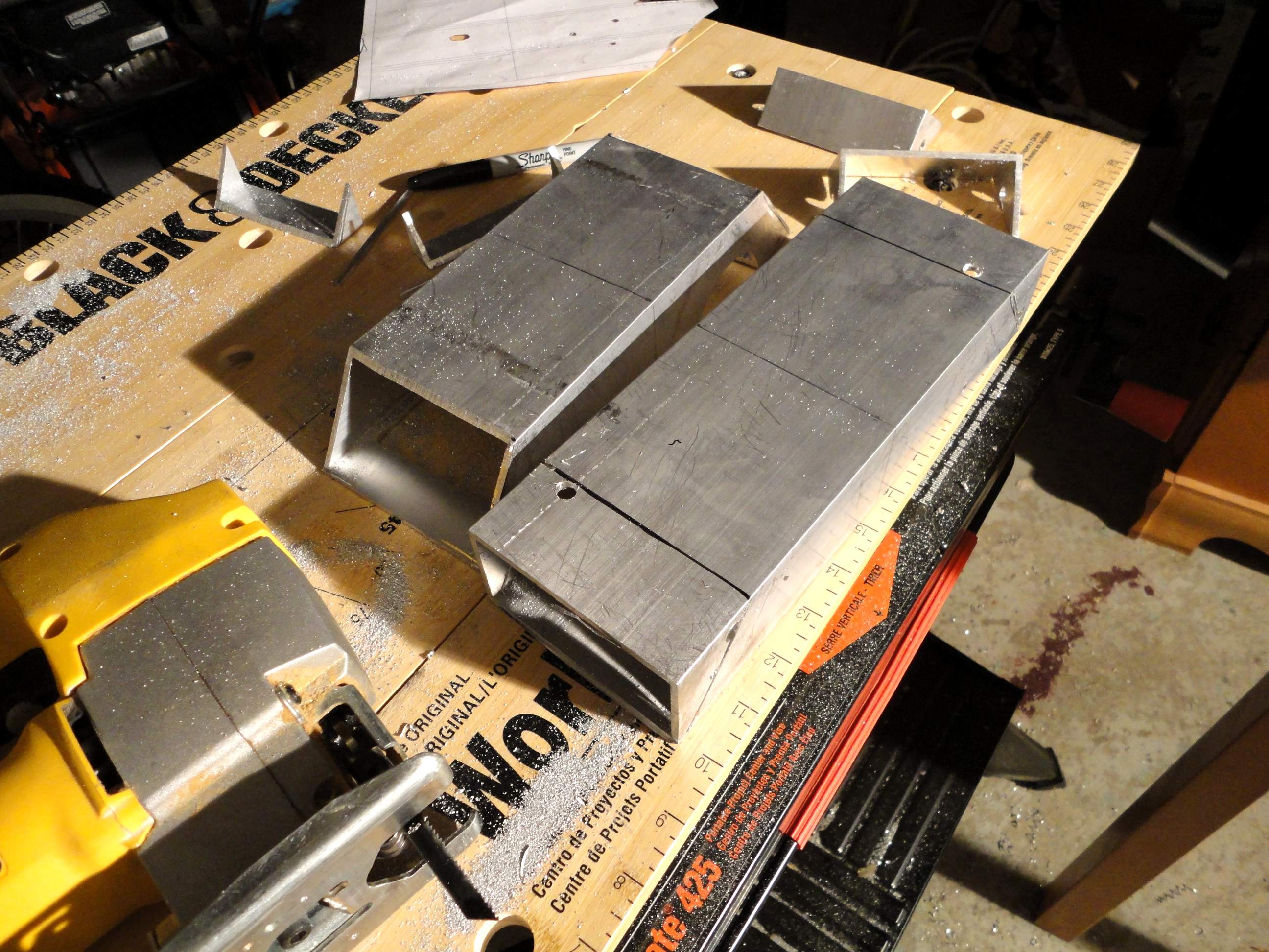
8013.JPG
Angled cut vs straight
cut. Yes the angled cut looks
nicer but the whole thing looks rough anyways and it will be hidden so the
choice is up to you.
|
|
8014.JPG
Upper and lower view of the top piece.
|
|
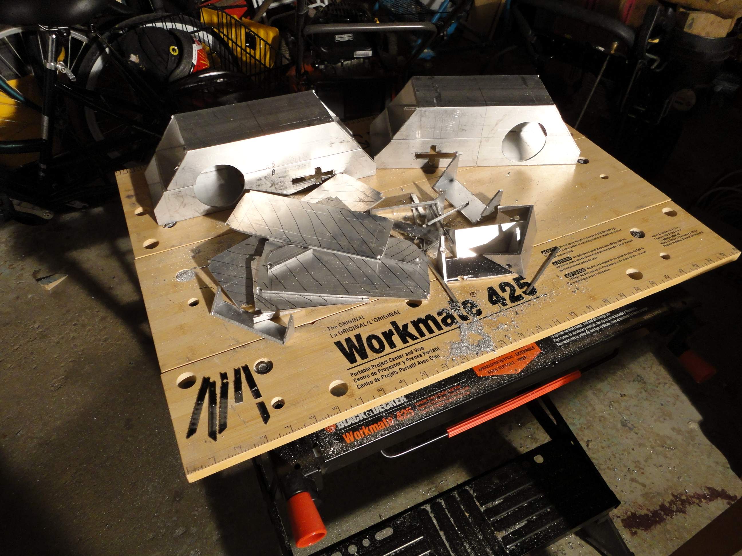
8015.JPG
Finally done.
Left and right drive assemblies
|
|
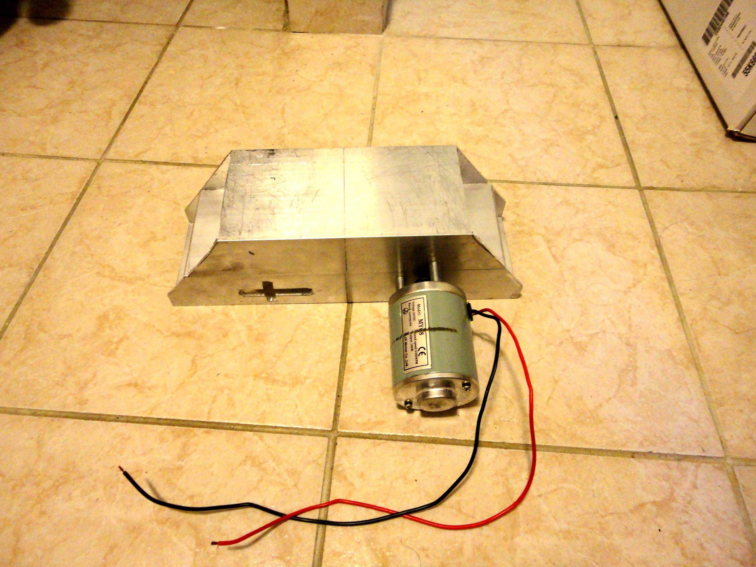
8016.JPG
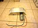
Test fitting the motor to the holes drilled to make sure
they fit. Note: The motor I got the scooter from has
the longer screws and spacers that I used here to mount the motor to the
drive system.
|
|
8017.JPG
Just to show the other side.
|
|
8018.JPG
Another view.
During the final assembly I actually had to open up the circle a bit
more as part of it was hitting the motor housing.
|
|
8019.JPG
Another view
|
|
8020.JPG
Top view
|