Lighting your Model
This was supposed to be a quick tutorial on adding lights to your model. I guess I have done it so many times that I did things automatically. However as I was writing things down it got longer and longer. Hopefully I remembered everything and that this tutorial is hlpful.
I like using LED lights because they last longer then incandescent ones and also run cooler. There would be nothing worse then going through all the work finishing your model and then having a light burn out.
What prompted this tutorial was the idea of adding lights to the cockpit of an Eagle. That is the reason we are using 2 LEDs here. For your application you can add as many LEDs as needed
Here are the basic tools needed
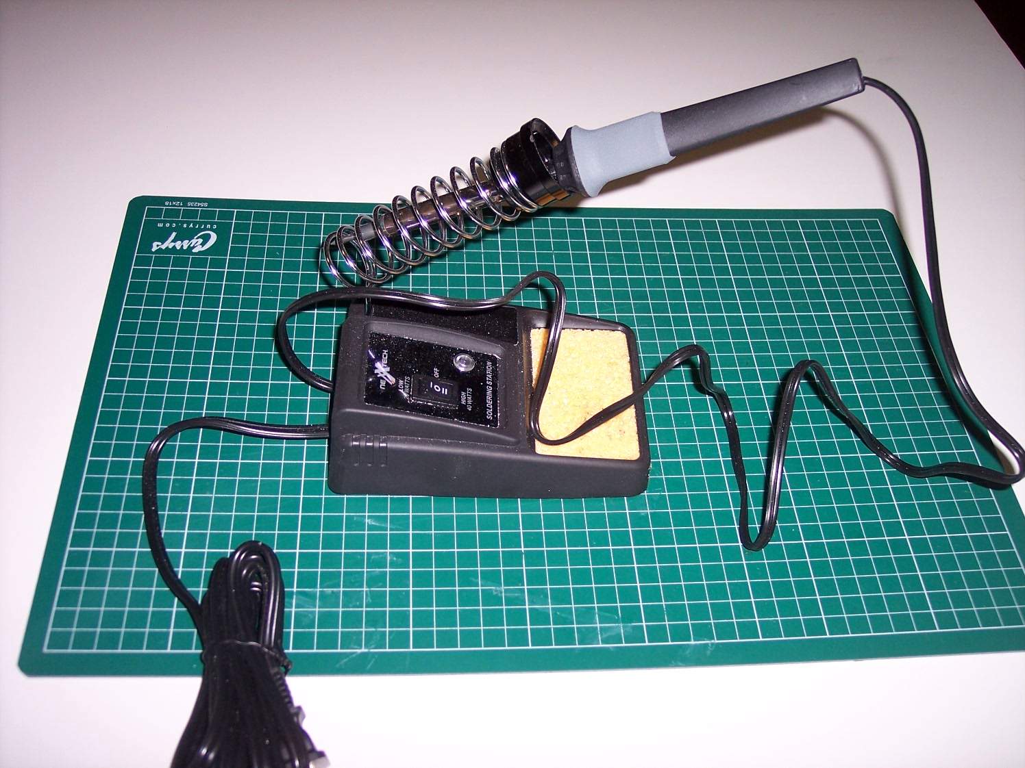
Soldering Iron - This is a dual 15 Watt - 40 Watt unit that cost me $15. Nothing special.
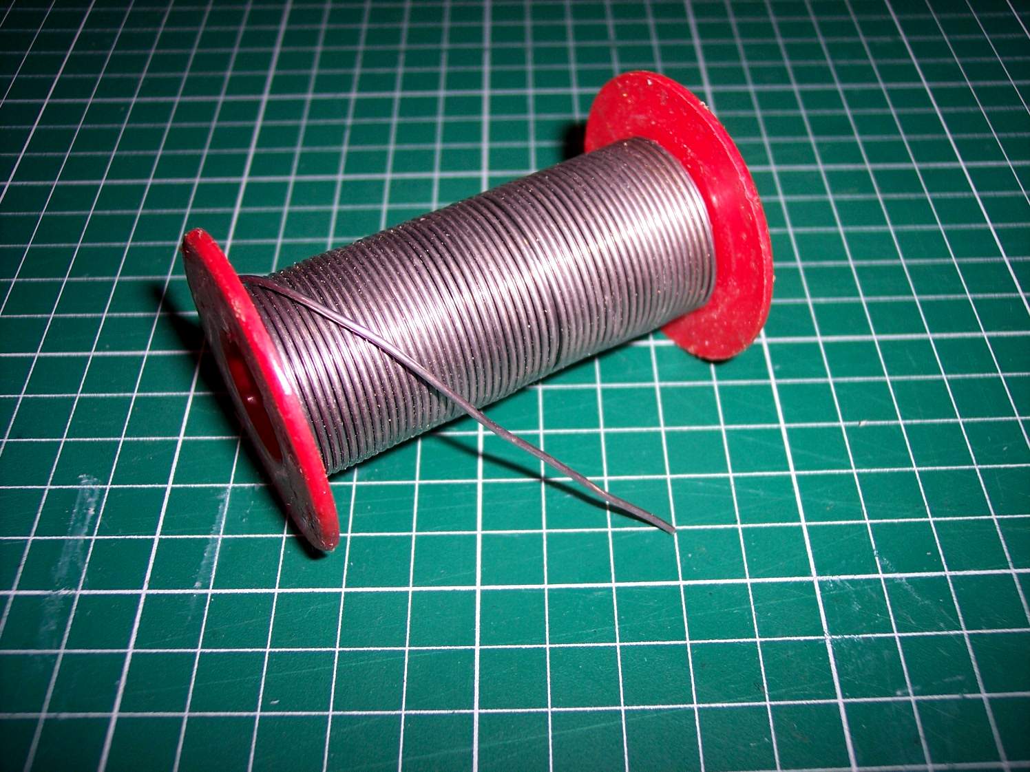
Solder - Nothing special here either. Lead free with flux in it to help the soldering process
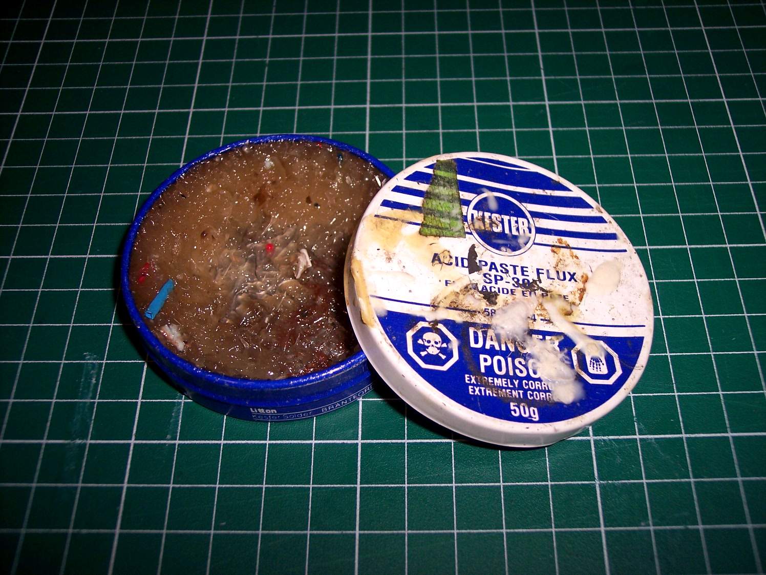
Flux - Used to help with the soldering process. It allows the solder to flow easier
Other tools that would make life easier but is not essential
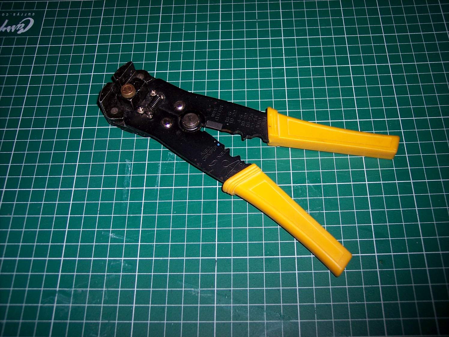
Wire stripper - I do a lot of electrical work so I invested in a decent wire stripper
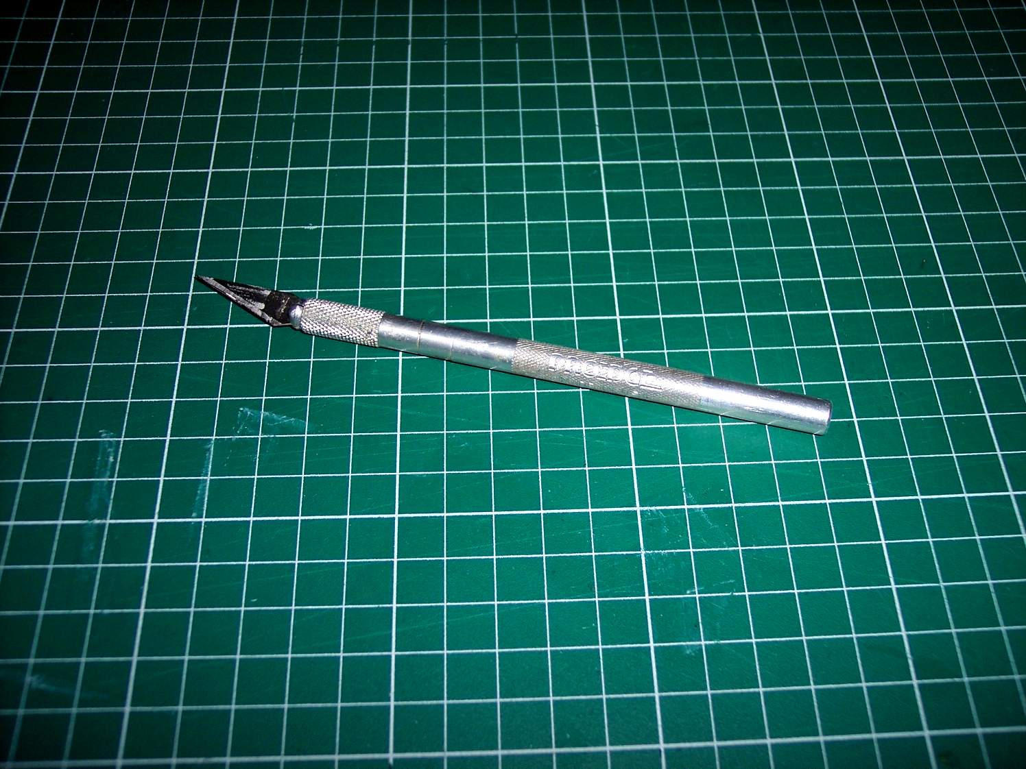
Xacto knife - you can use this to strip the wire ends if you do not have a dedicated wire stripper
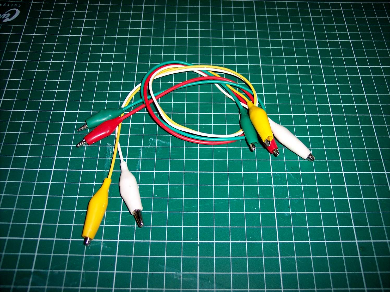
Test Leads - Test wires let you try things out quickly and to make sure everything works before soldering things together
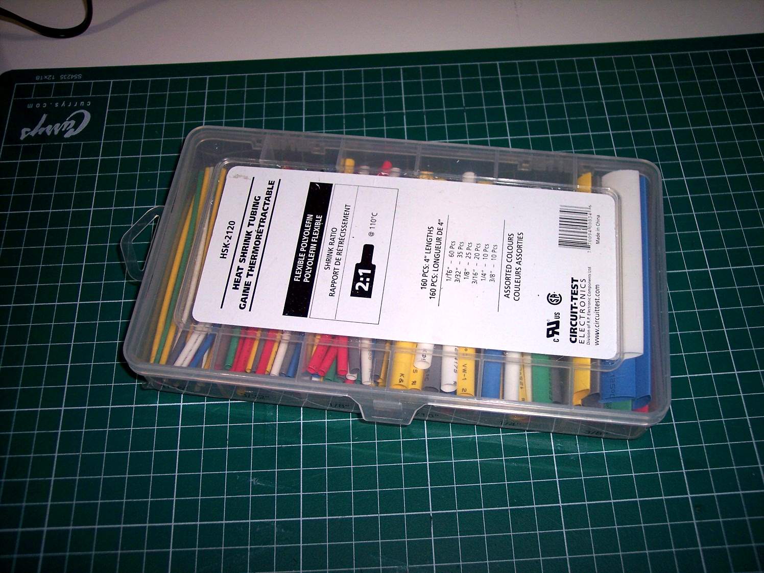
Heat Shrink Tubing - This comes in various colours and sizes and is a nice and neat way of covering your exposed wires
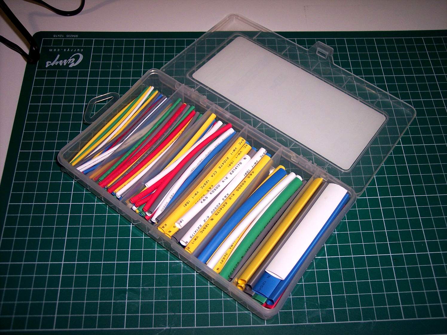
To use it you cut a short length, Cover the exposed wires and then apply heat (match or small torch). The tubing will then shrink and provide a nice clean seal of the wires
Other items you can use but are not shown - Electrical tape - to cover exposed wires if you do not have any heat shrink tubing
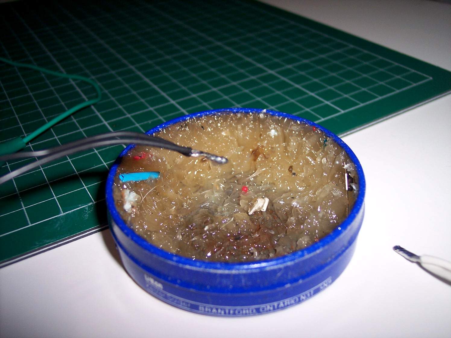
Hot Glue gun - used to stick the wires or LEDs into position in the model
Bill of materials
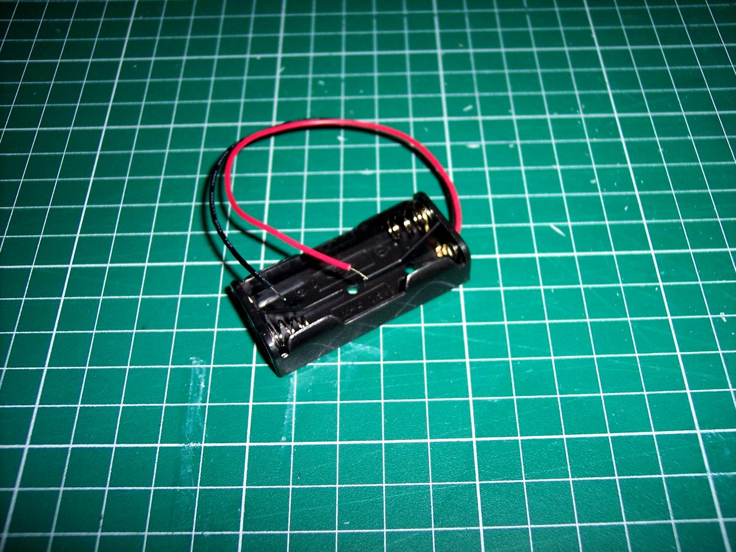
Battery Holder - I am using a (2) AAA battery holder. This will give me 3 Volt DC and is perfect for the 3.3-3.5 Volt DC LEDs I am using.
Resistors - Some use resistors in their circuits. Since all my LEDs are the same voltage and I am using the correct voltage, I will not use any.
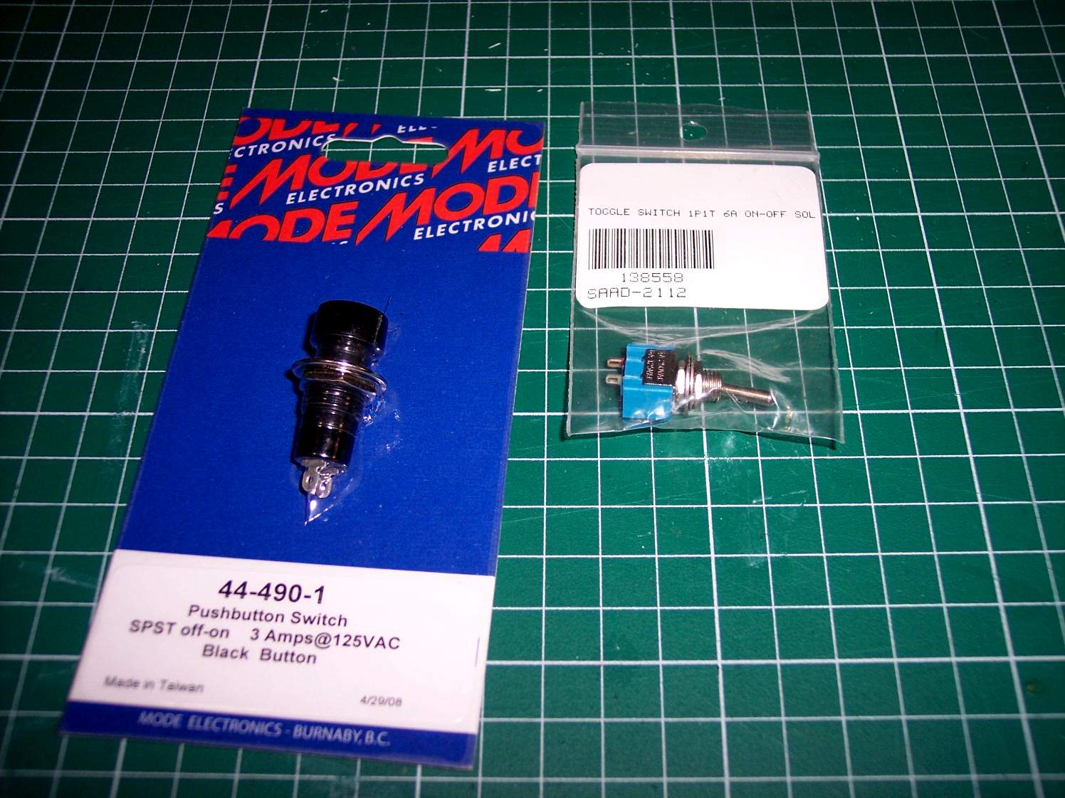
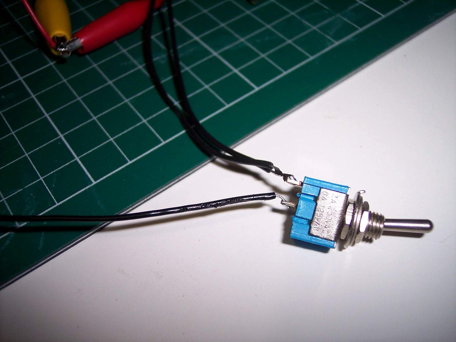
Switch - The switch I am using is a toggle on/off switch (right). Also shown is a Push on/off switch (left). The toggle switch is much smaller that are more easily hidden. There are other switches that are momentary on or momentary off. This means you would have to push and hold onto the switch to turn things on or off. For our application we do not want to use one of these type of switches.
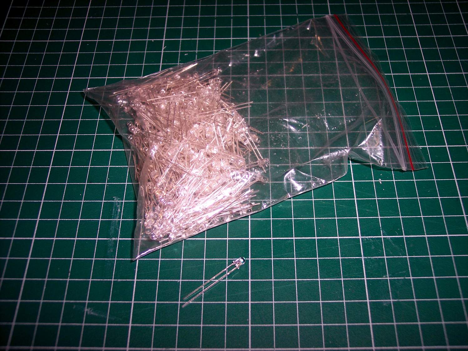
LEDs - I am using some 3mm super bright white LEDs. They are 3.3-3.5 Volt DC and come in sizes 5mm and 3mm. Note that one end of the wire coming off the LED is longer then the other. There are various colours and Voltages for LEDs
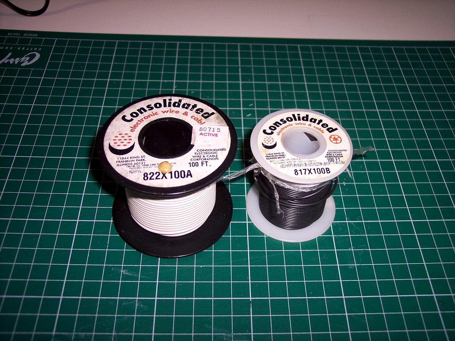
Wire - Almost any type of wire will do but I am using multi stranded 18-22 Ga wire. I can use multiple colours or only one colour
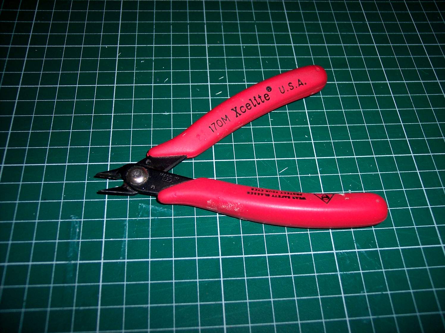
Snips - I use these to cut the wires to the length needed
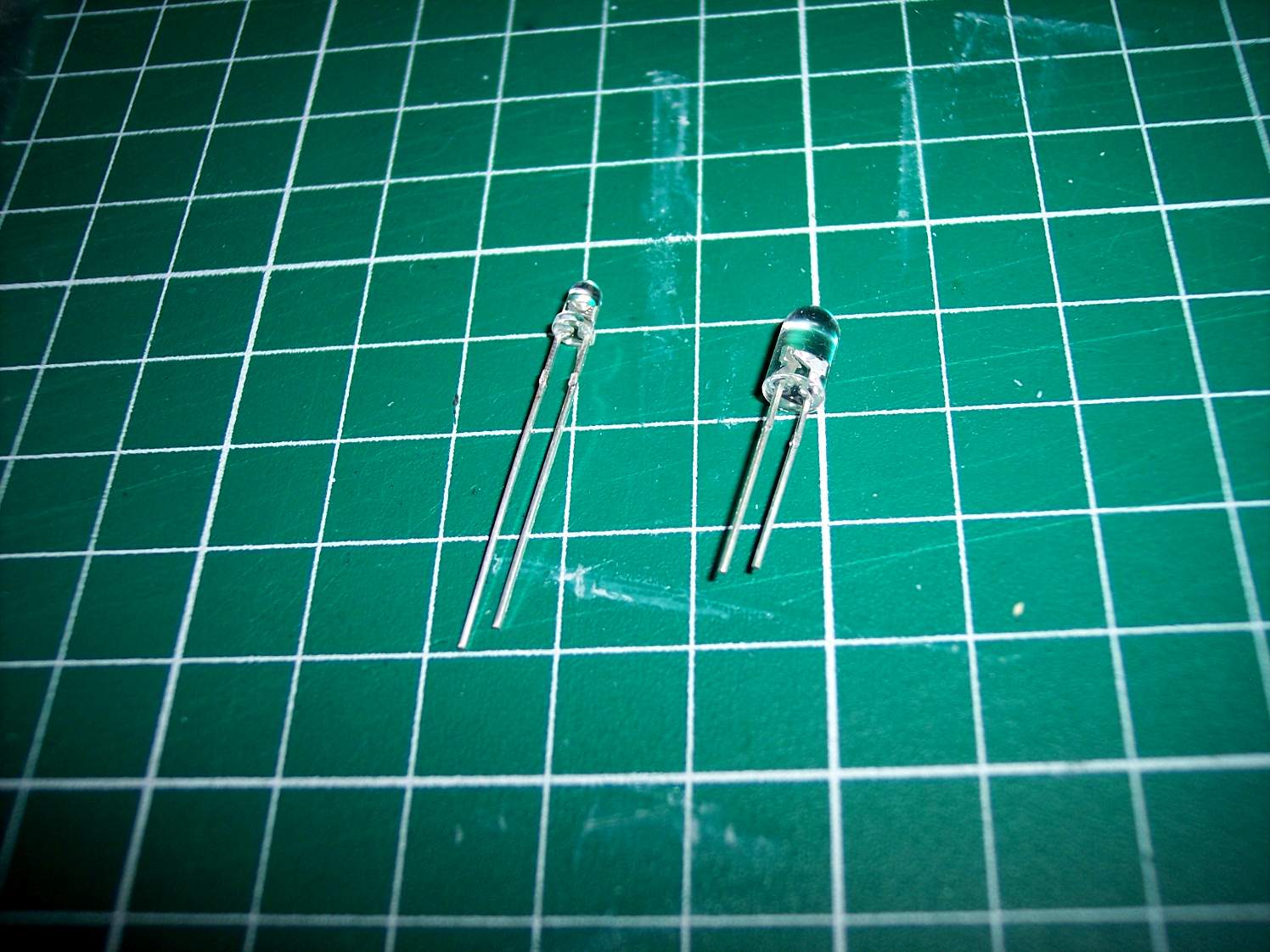
Here are the 3mm and 5mm LEDs as a size comparison
I will show the step by step procedure for making the circuit.
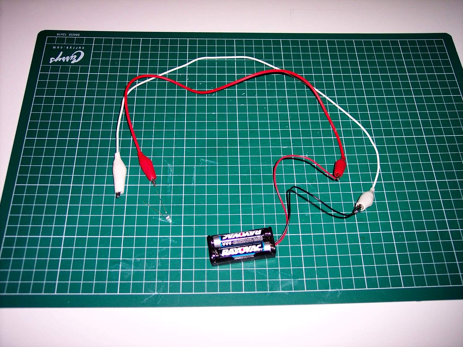
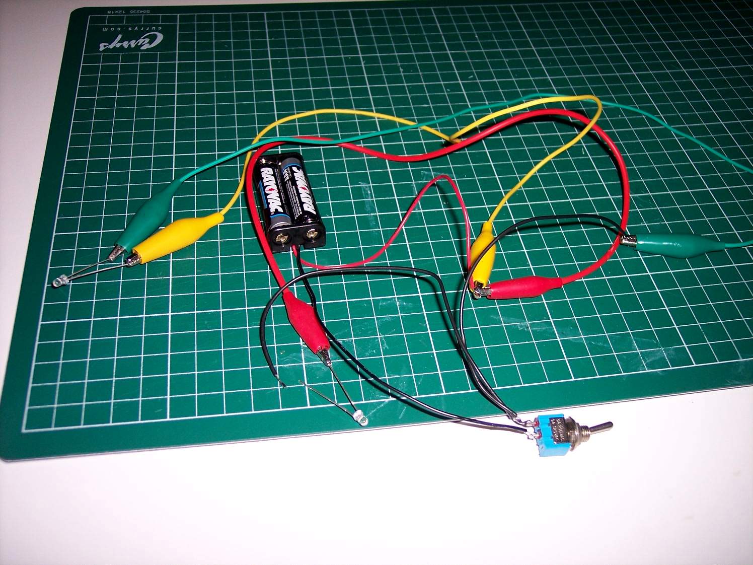
Using the test leads wire up the battery holder and one LED as shown
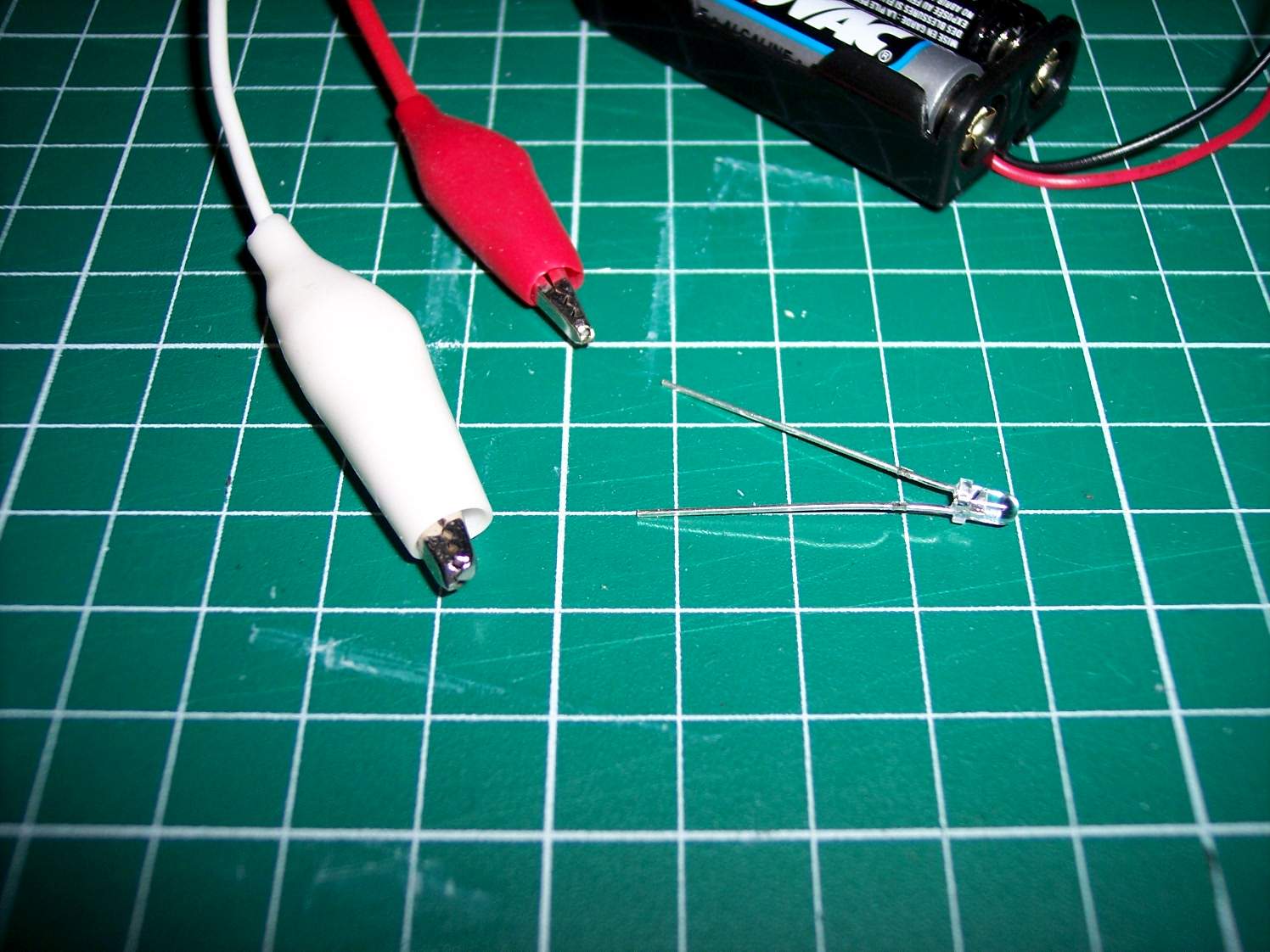
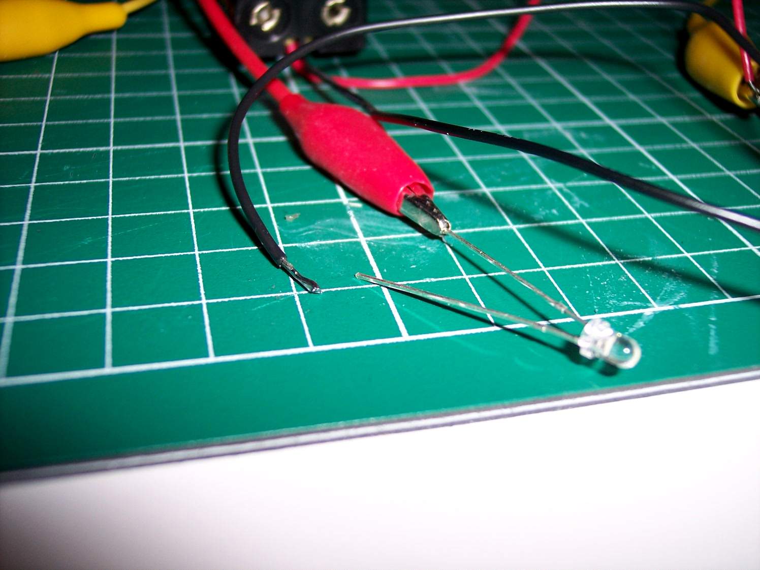
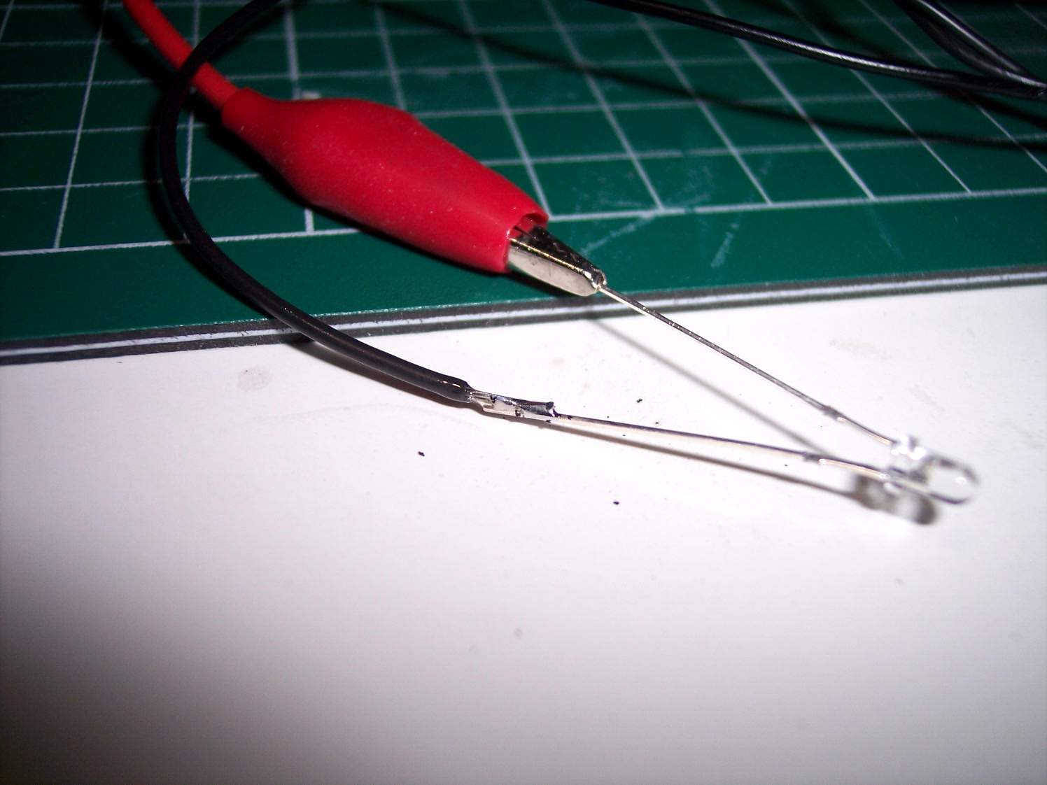
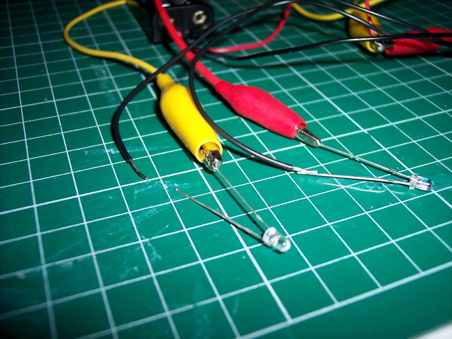
Close up showing one test lead (red) clipped to one leg of the LED while the other one is not connected yet
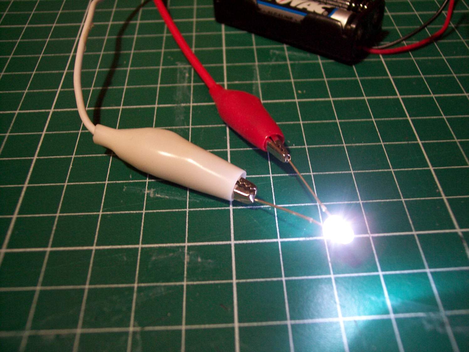
Touch the other test lead (white) with the other leg of the LED. It should light up if it is wired up correctly. If the LED does not light up switch the colour test leads with the LED legs. If it still does not light up either the LED is bad or the batteries are bad. A quick touch will light up the circuit and is all you need to prove it works. Here I clipped it on so I could take the photo.

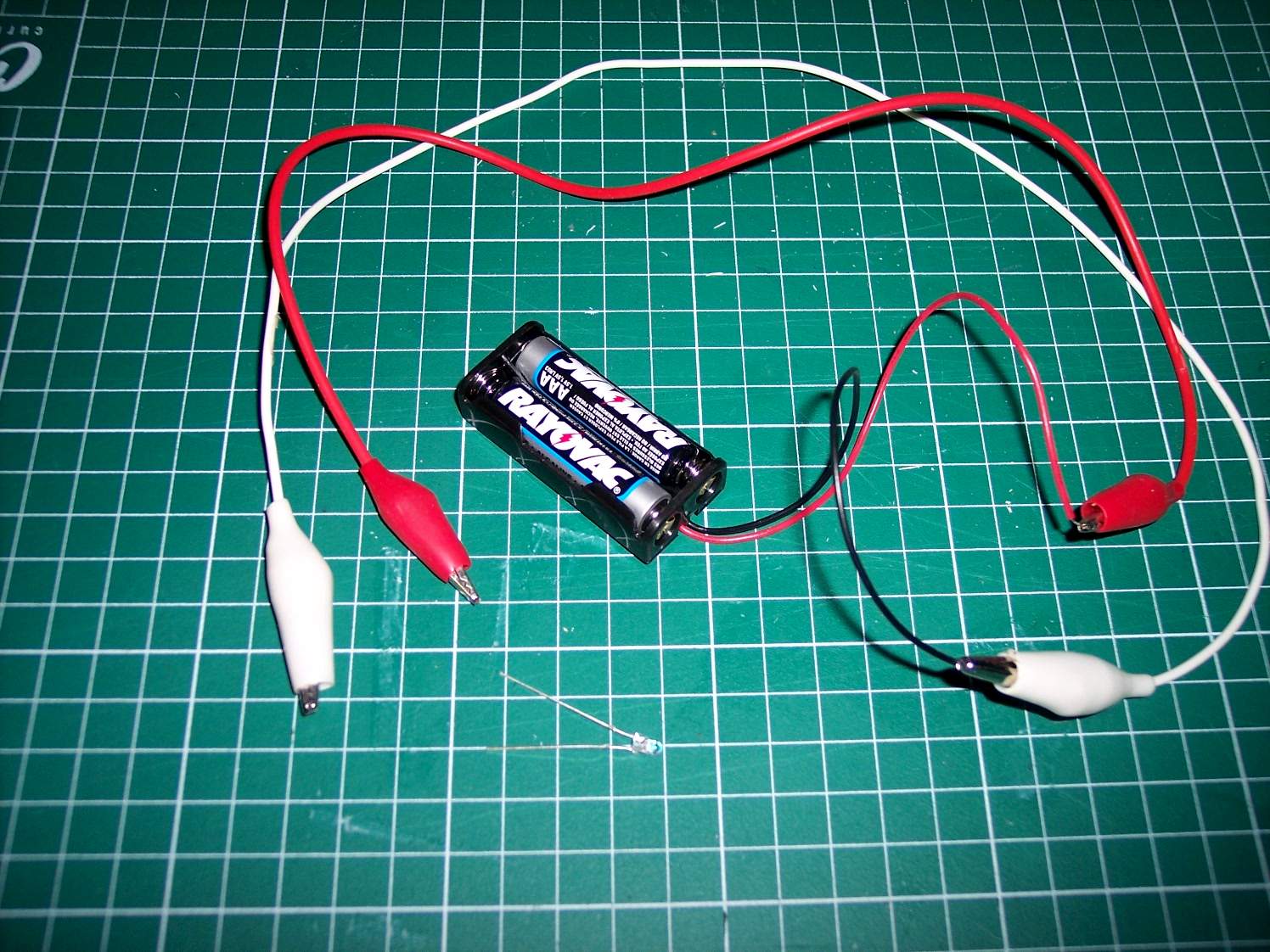
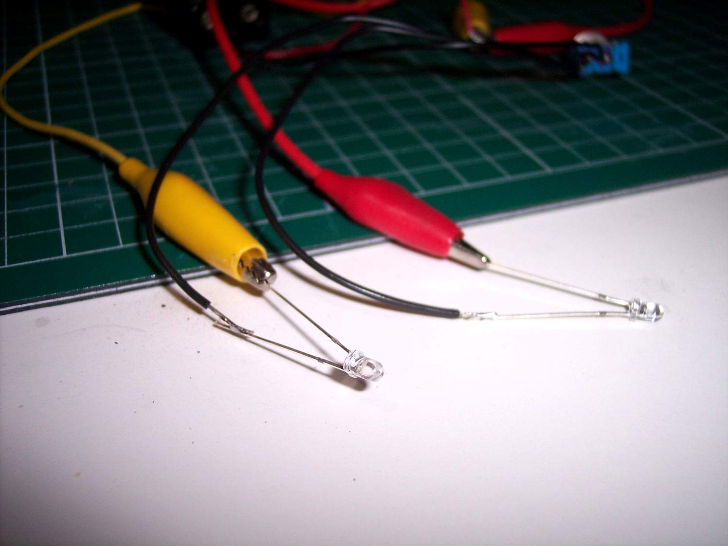
Now we add the second LED with the yellow and green test leads
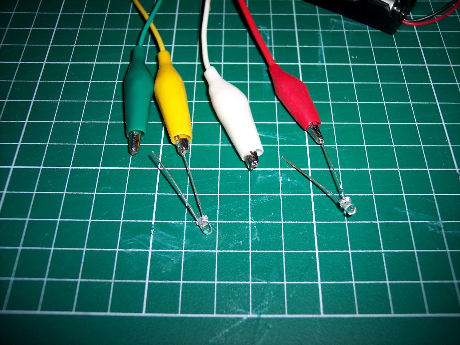
Again one leg of the LEG is clipped on while the other one is not attached yet
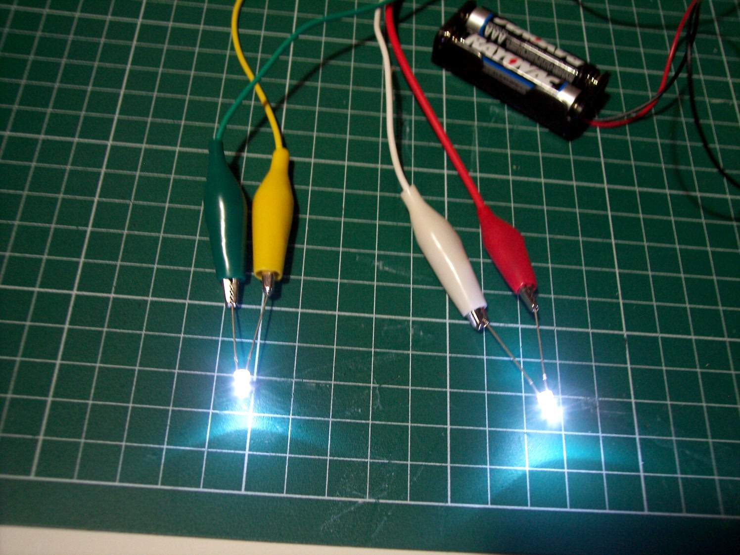
Quickly touch the other leg of the LED quickly with the second test lead. If it does light up you can clip on the test lead. If it doesn't light up then switch the test leads and LED legs.
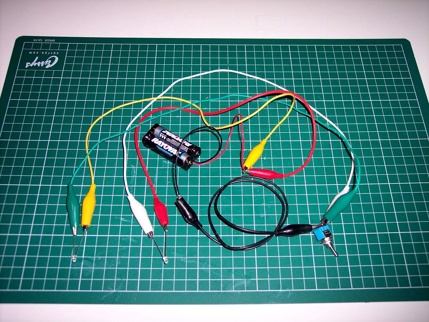
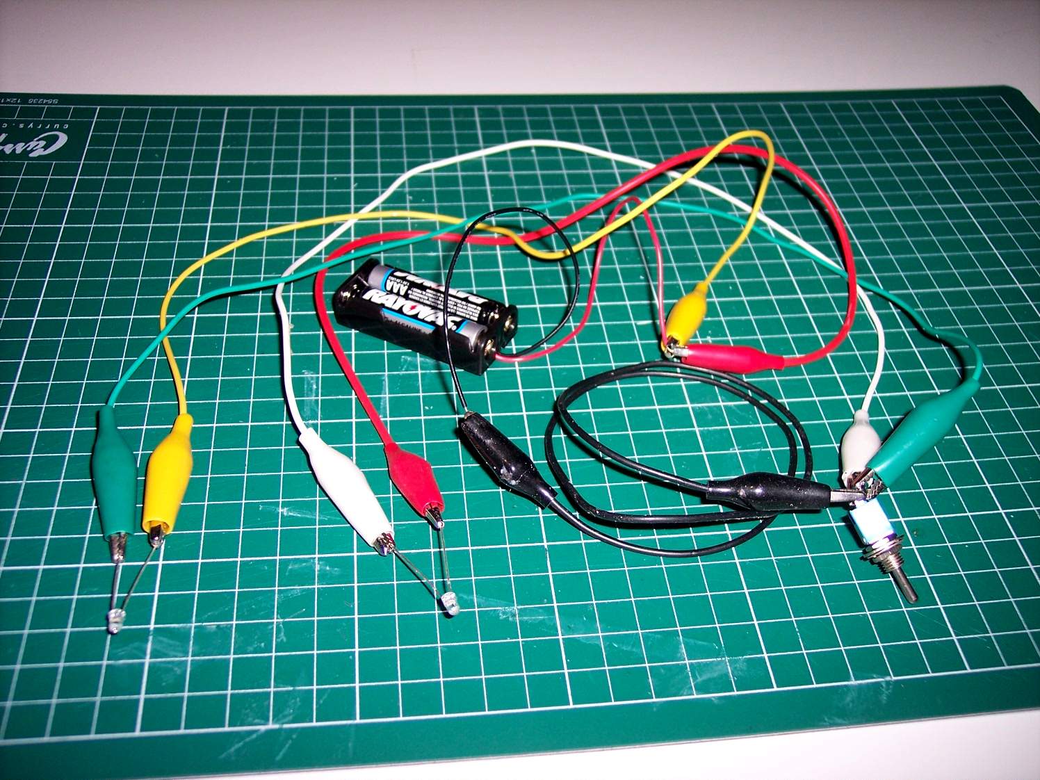
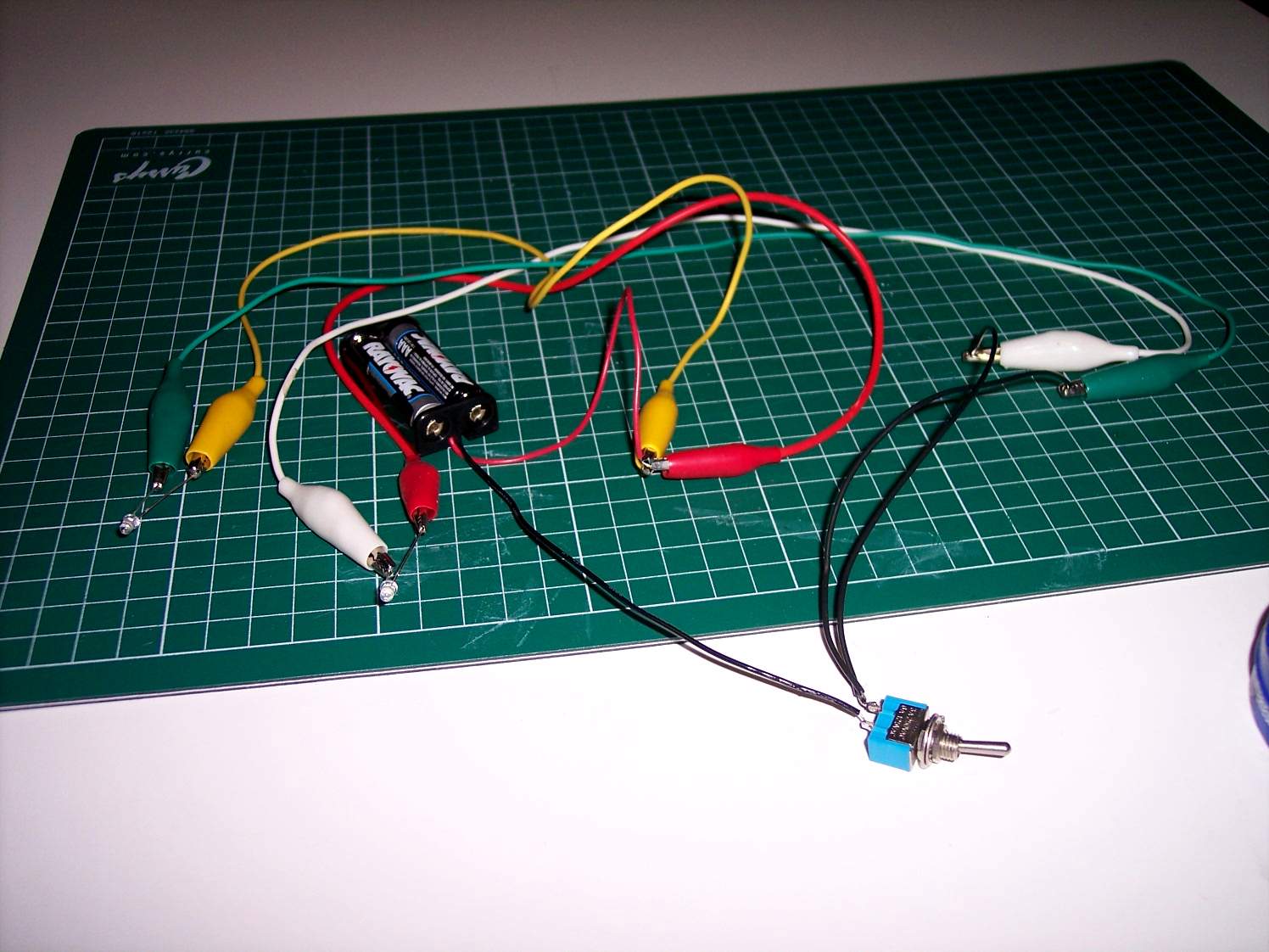
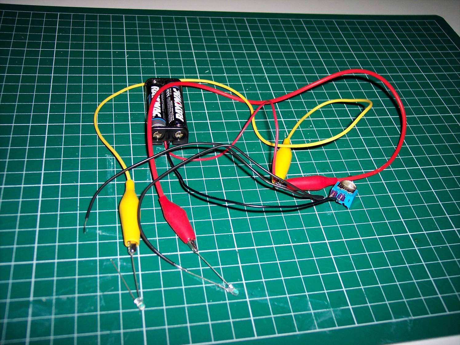
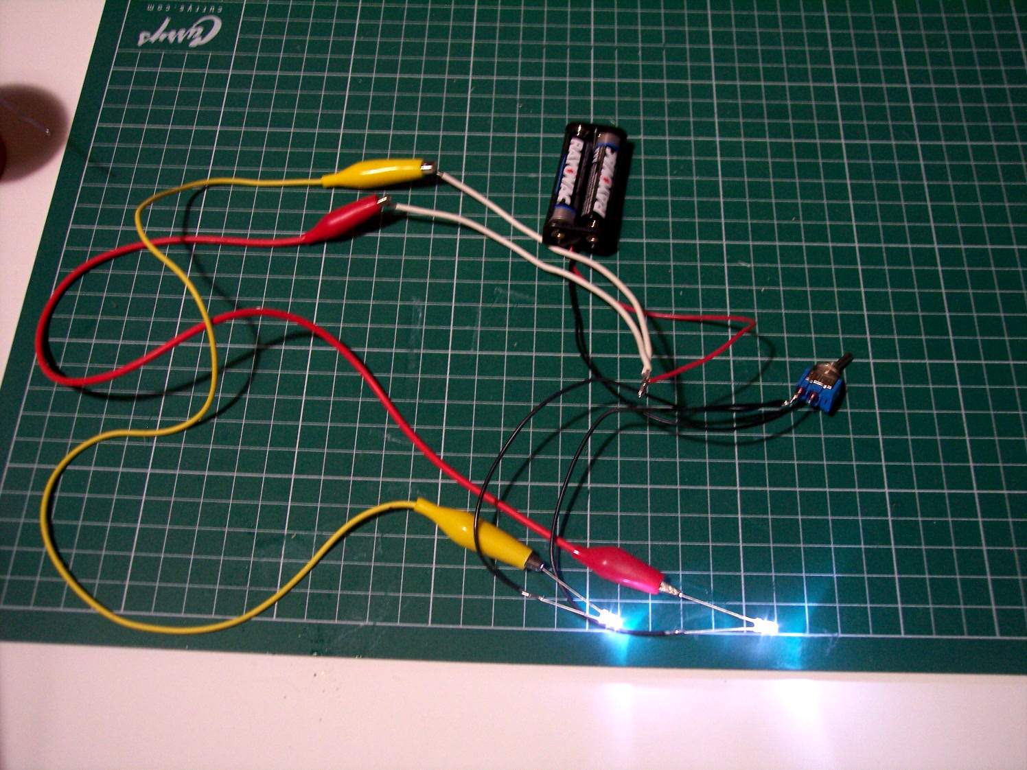
Now we add the switch and the black test lead to turn the LEDs on and off

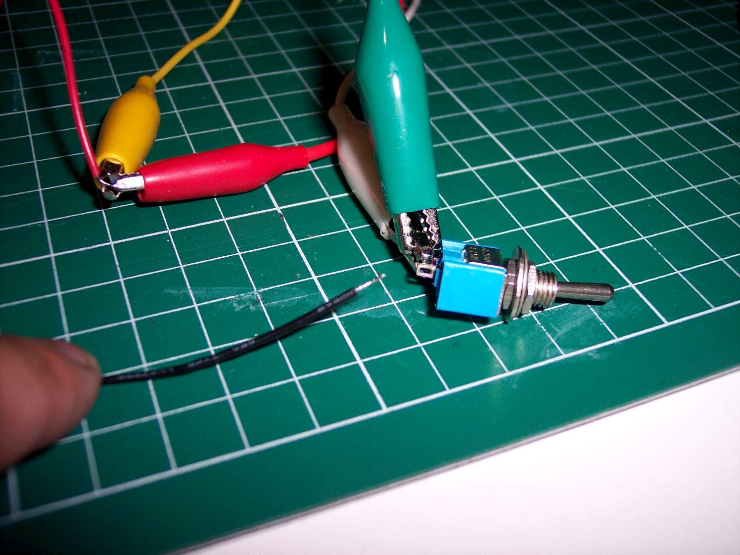
Close up of the switch. The black teat lead goes to one side of the switch while the green and white test leads go to the other side of the switch
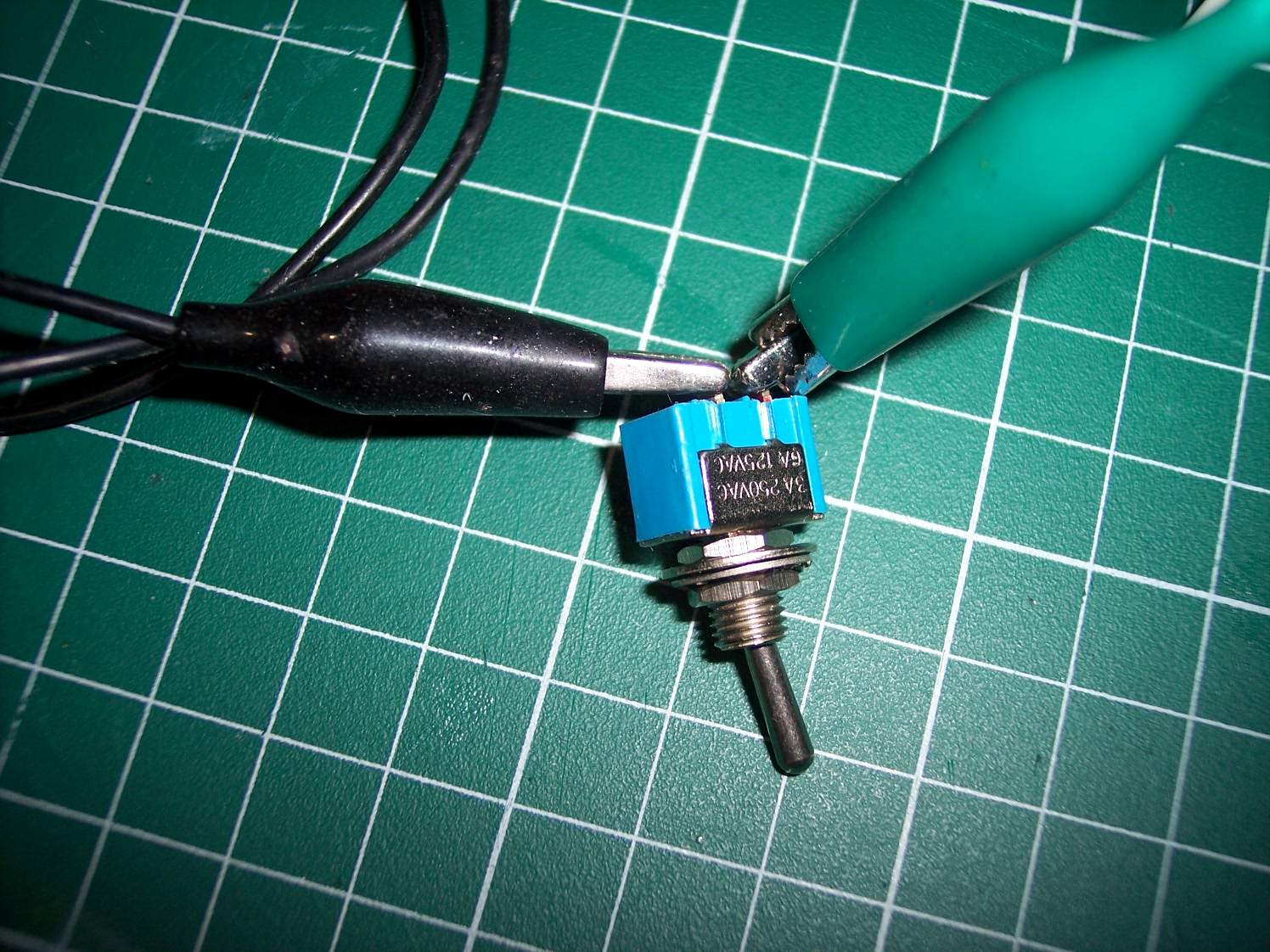
Another view. The white test lead is hidden by the green test lead
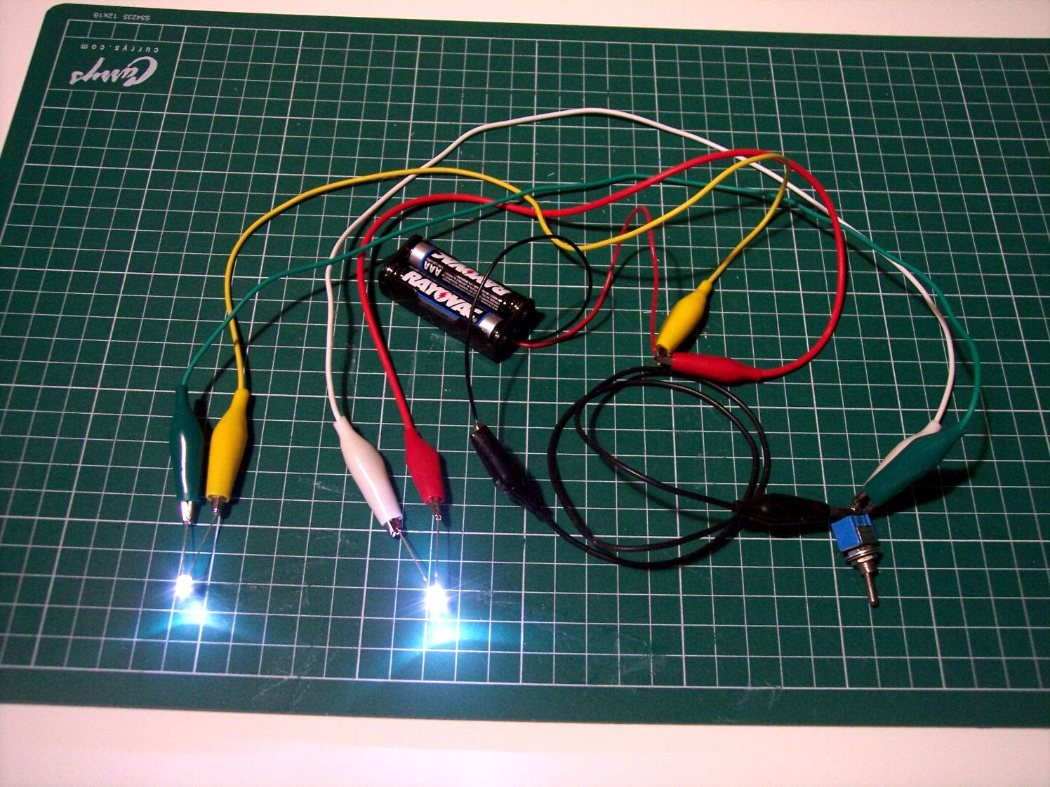
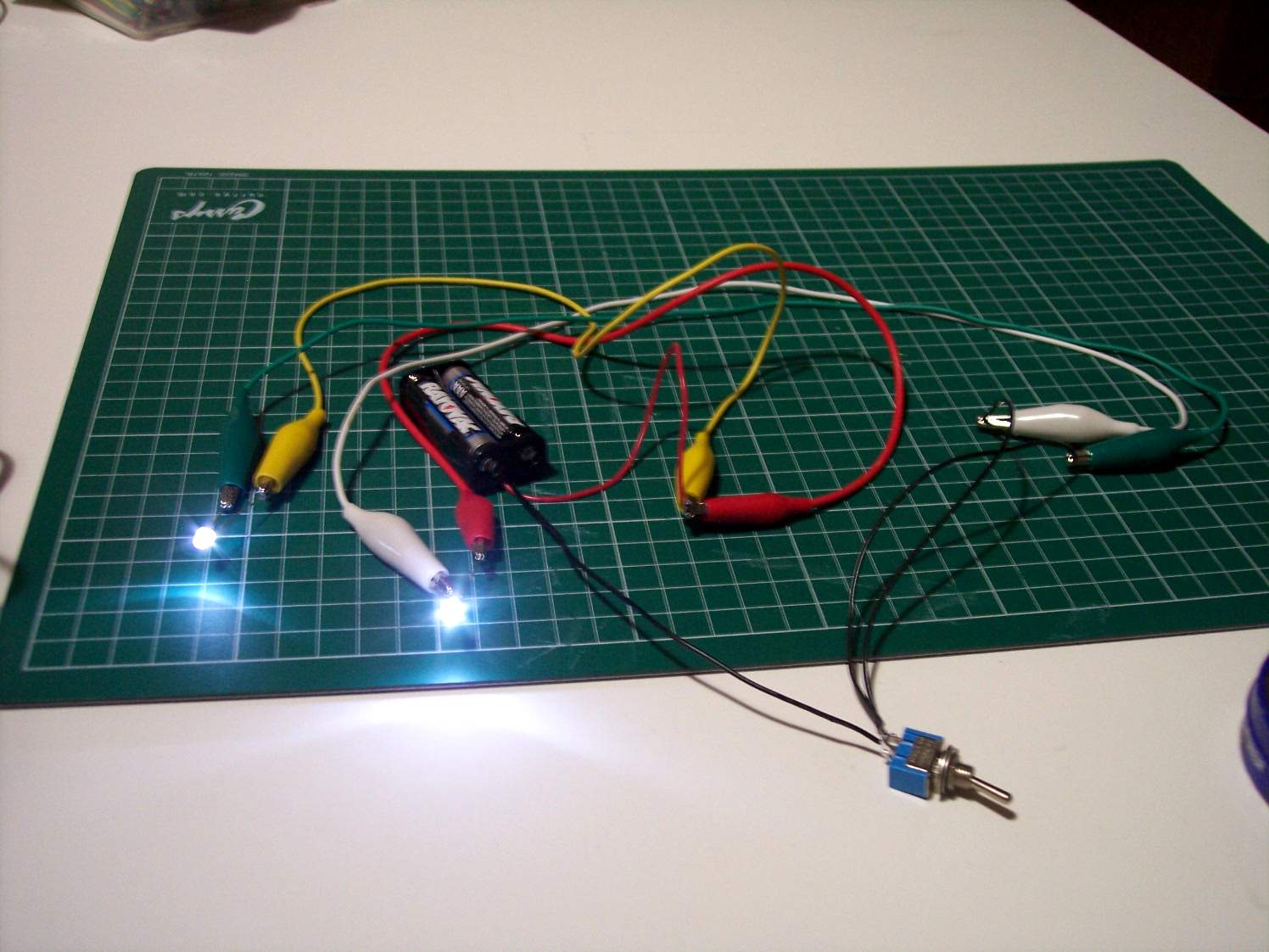
If everything goes well the LEDs should turn on and off using the switch

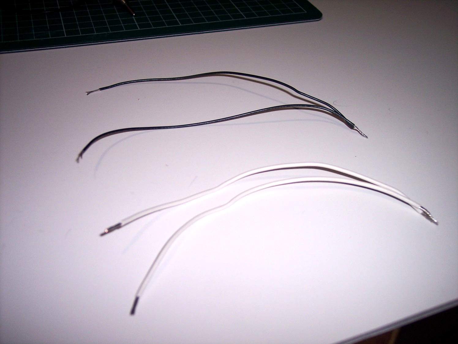
We will now switch the test leads for wires. Here I have cut 4 wires the same length. To help visualize the wiring I have used 2 white and 2 black wires
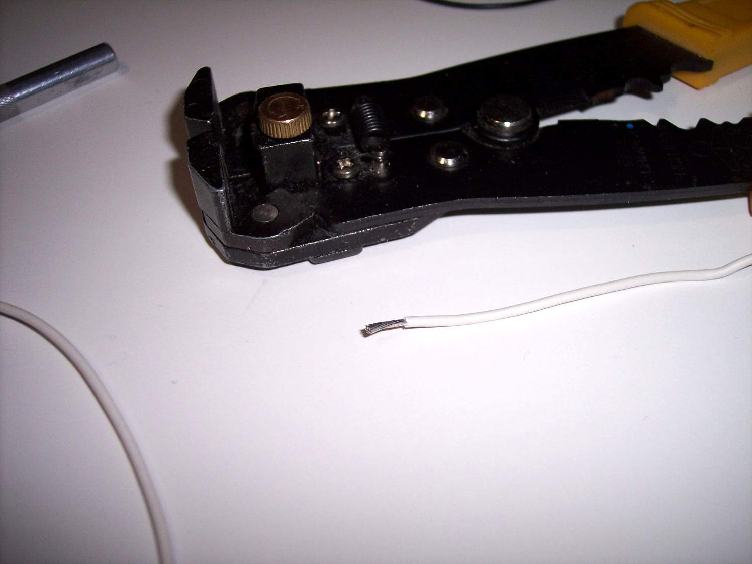
Stripping wire
If you do enough circuits you might want to invest in a decent wire stripper. It is not that expensive and does a great job compared to the plier type ones. Even then I sometimes use just an exact blade and strip the wire end

Here is an example of the end being stripped using the Exacto knife
I then twist the ends of 2 sets of wires together
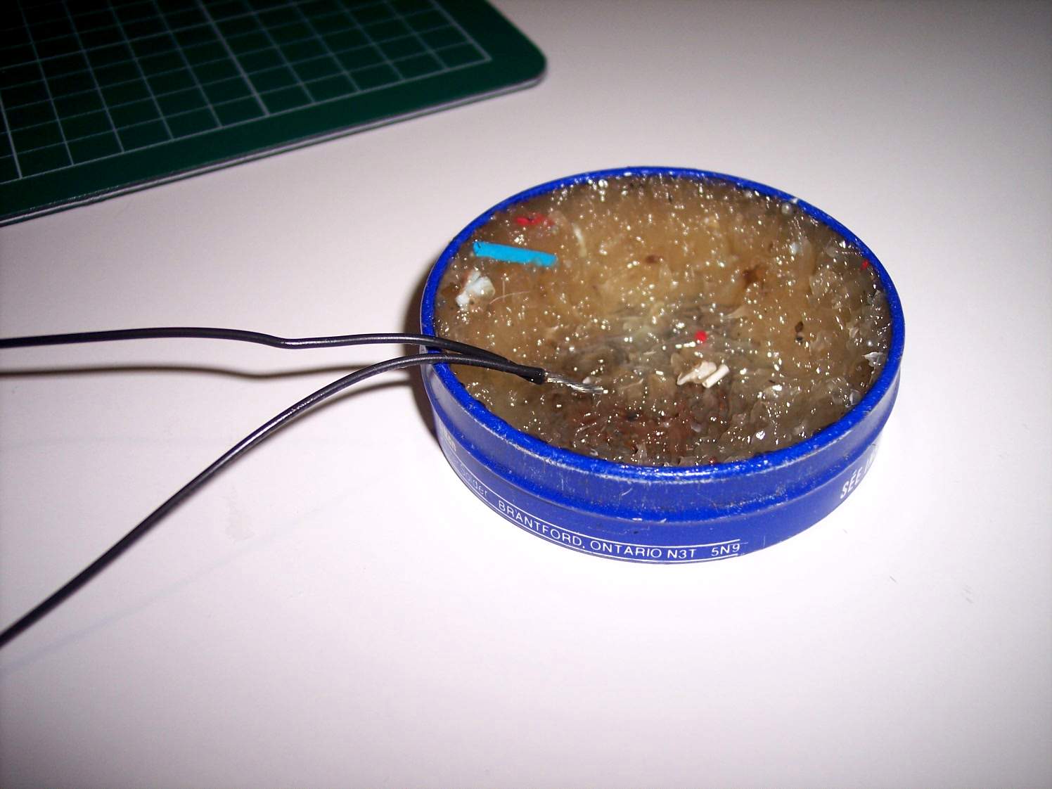
I then dip the exposed wire ends in the flux

Here is my soldering iron and solder I am now going to use

When the soldering iron is hot enough I will touch the end to the solder
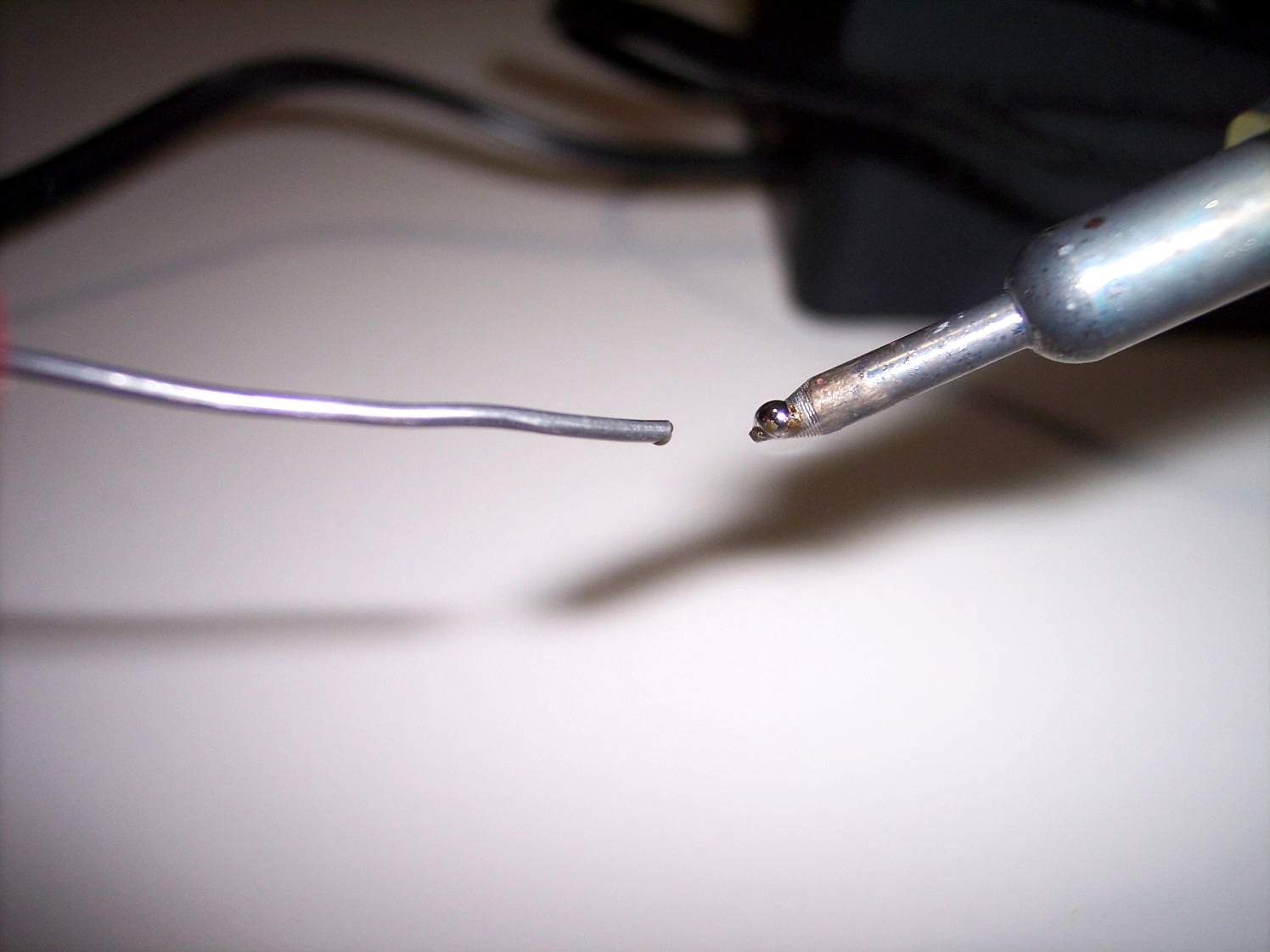
Melt a small bit of solder onto the end of the soldering iron
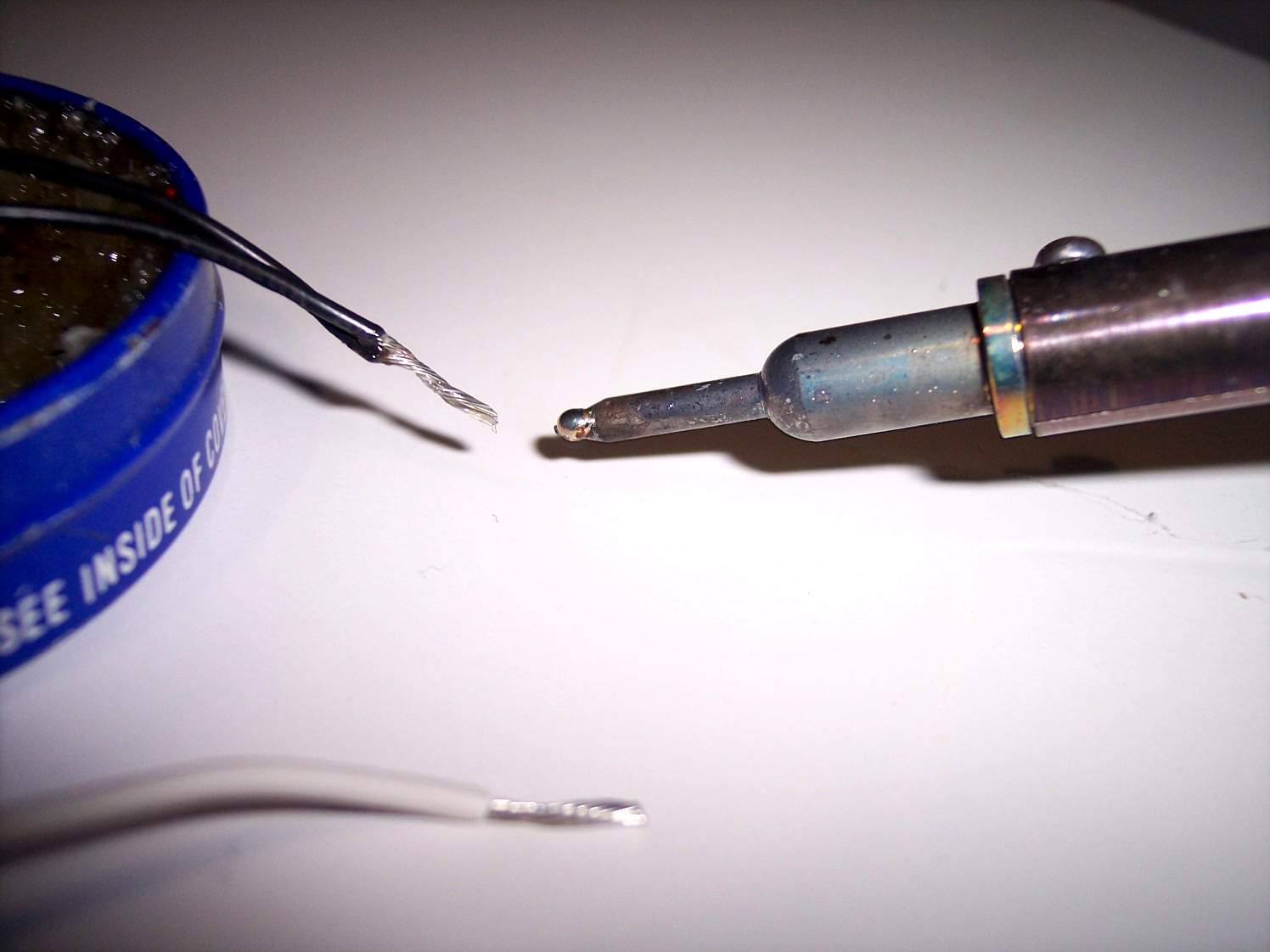
Then touch the solder to the end of the fluxed wire
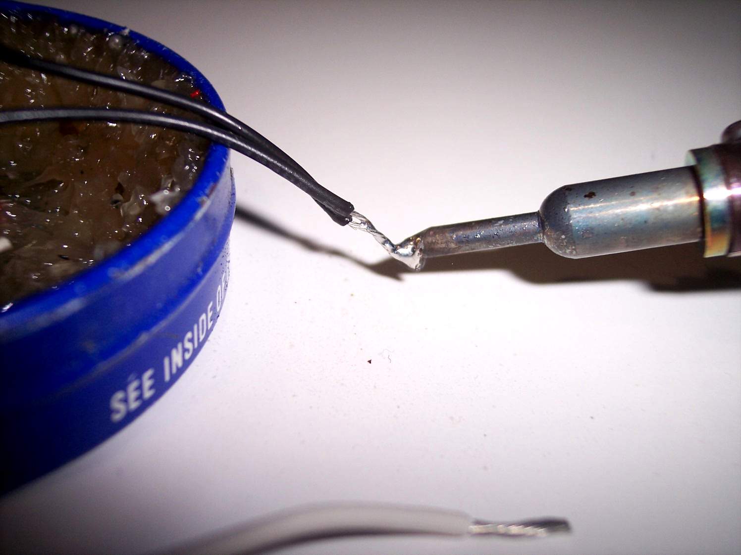
The solder should flow into the wire
Our first step is to take out the black test lead
Here I fluxed the end of the wire from the battery holder and will solder it to one end of the switch
The end of the wire is hooked into the little hole in the switch tab

Some solder is put on the end of the soldering iron and is ready to be touched to the wire with the flux
We again flux the wire that we added solder to before soldering again
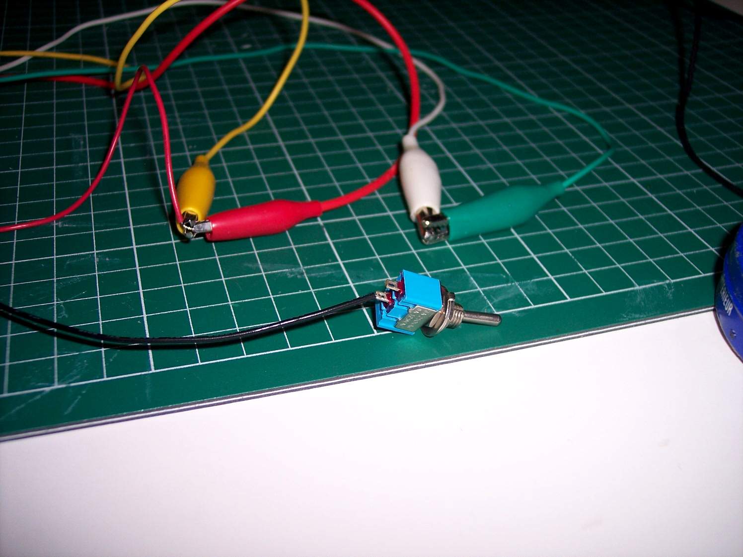
Here it is after soldering the dual wires to the other end of the switch
Here we run a test to make sure things are still working. Clip the test leads to the end of the newly added wires
Using the newly soldered in switch we can turn the LEDs on and off
We then remove the white test lead and will solder the back wire directly to the LED
Again don't forget to flux the end of the wire before soldering it to the LED
Here we are with the wire soldered to the LED leg

Here is where we are with the circuit so far
Now we are going to replace the green test lead
Close up of the wire ready to be soldered together. Again add flux to the end of the black wire before soldering
Close up of the wires soldered together

Now we have soldered the dual white wires to the end of the red wire from the battery box
Again we test the circuit to make sure it is still working

We remove the red test lead and solder the white wire to the other end of the LED leg. Flux and solder
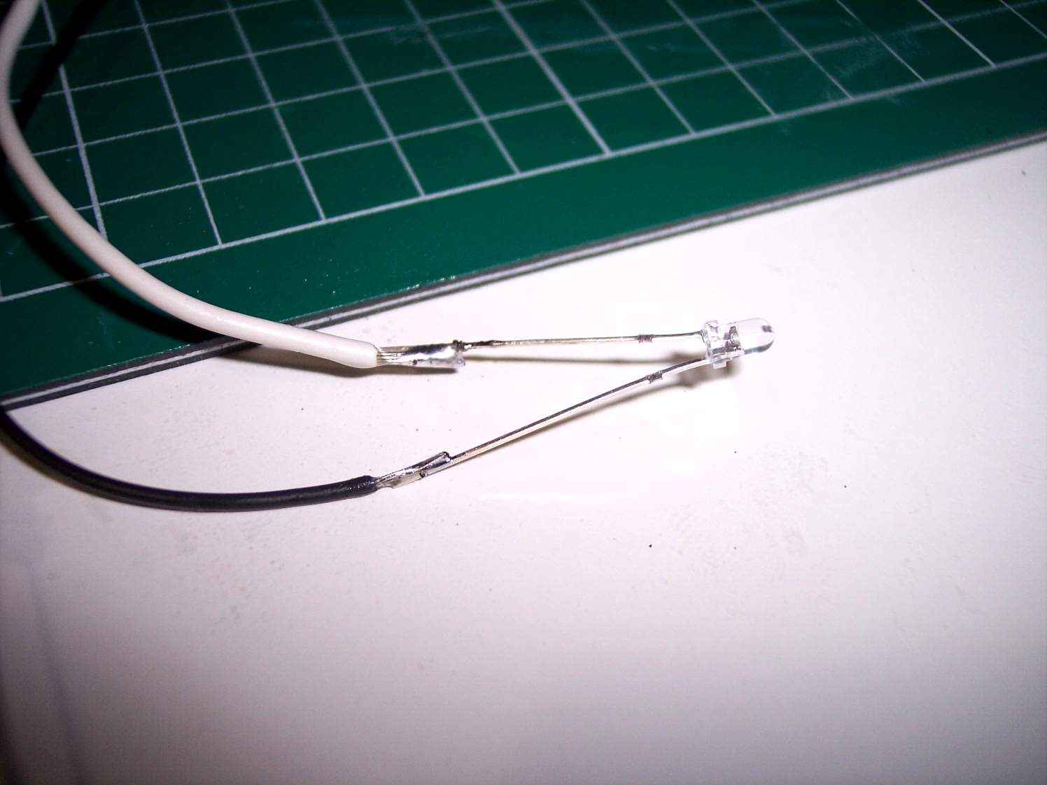
Close up of the white wire soldered on. I have spread the legs of the LED apart so they will not touch. Repeat with the yellow test lead

Here is the entire wiring circuit all soldered together
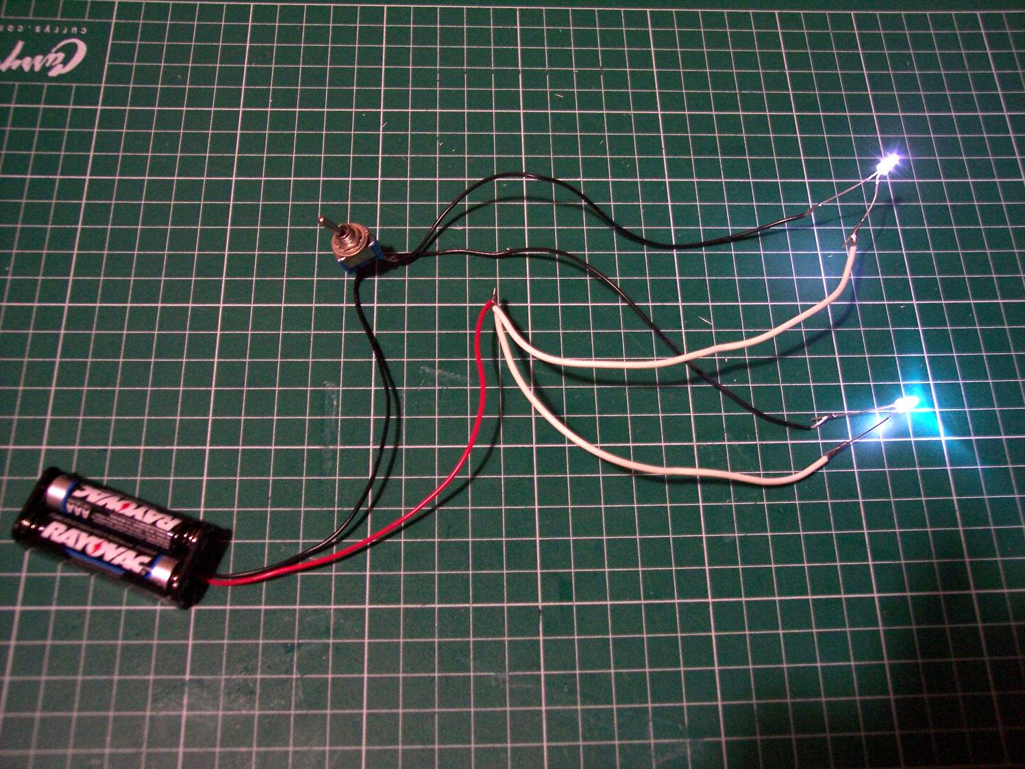
One final test is done to check that the LEDs work
Next you have to covering the exposed wires. Here is where I use the heat shrink tubing but for now you can use electrical tape or even masking tape.
Switch Warning
Be aware of how the switch is mounted. Some switches can be mounted from behind while others have to be mounted from the front before you can solder the wires in. The toggle switch I have here can be mounted from behind while the other switch (Push on/off) is mounted from the front.
Advanced
You can use a limit switch or a NC momentary switch and wire it up to the landing gear. So when the eagle is touched down the movement of the landing gear will keep the lights off. However if you lift the model up this activates the switch and turns it on.
Fiber optics
In some cases you can use fiber optics to direct lights to other areas of your model. One example is to use one LED as a light source and then use fiber optics to direct light to several places in your model.
More advanced
There are circuits out there that can give you blinking light and even sound but that is another story.