BRAKE DETAIL
March 24, 1999
The brake detail in kits varies from nothing to very nicely detailed. Some people may question why we want to add detail to an area that is usually covered or hard to see. Most of the time these will be covered but some modern cars have wheels with very open areas where the brakes can be seen.
Note that this section is relatively new so I am sure there are errors all over the place. If there are any explanations that are confusing please e-mail me so I can fix or improve them. Any suggestions are also welcome to add to this section
DETAIL LEVEL 1 - MODERATE
This involves no modification to the actual kit part and only involves painting and minor detailing. This section can also apply to the more detailed sections.
Using the right paints will make the disc look very realistic. For modern f1 cars the disc are carbon fiber or some other exotic material. Tamiya suggests a mixture of their Gun Metal and their flat base. It doesn't take much flat base to turn the gun metal flat. When airbrushed on the finish looks very good. I don't know of any other paint combination that produces this finish for carbon fiber discs.
For older F1 cars with metallic discs the best paint I can recommend is the Testor Metalizers or the SNJ paints. These can be buffed up to a very realistic metal finish. Care should be taken not to handle these surfaces since they can lose their shine very easily.
Next are the calipers. Most of the time these are a bronze colour. Again I find the Testors Metalizers and Humbrol metals are good here. I find the Tamiya metallic paints don't look very realistic due to the grain size in the paints.
LOGOS AND TEMPERATURE STICKERS
Generally you don't see any temperature stickers with the wheel on so we won't cover this here. Generally the caliper has a manufacturers logo on the side of the caliper. If these are not included in the kit you can try and get some from another kit or make your own. The logos do not have to be exact since they are small and you are looking through the wheel. I will describe later on one method of making these logos.
For drilled disc you can use a small marker (0.05") or a wash to fill these holes in with black paint to make them looked like they are drilled through.
In 1:12 scale kits the discs are usually separate from the calipers. If this is so, you can attach the disc to a drill and spin it while slightly touching the paint. This will give it rings that look like the disc has been used. Personally I would not use this on the carbon fiber disc only the steel disc with Metalizer paints.
DETAIL LEVEL 2 - INTERMEDIATE
Here you want to take the wheel off and show off your work but you are not at the insane level (yet).
We will keep the kit method of mounting the wheels. In the next section you will want to make the wheels removable like they do in the real cars. See the tips section on uprights.
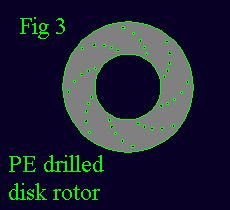
Painting is the same as outlined in Level 1. In drilled discs you can get a pin vice and drill out all the holes in the kit part. Since these indents are there already this process is fairly simple just a bit time consuming.
VENTED DISCS
This applies to almost all F1 cars, (modern and older models). As always check your references. These pictures can also give you a rough idea of the diameter of the holes and their spacing. Some discs have a slight recess where the holes are. I would advise not to try and put these in. This is very hard to do by hand and any slight mistake will look bad.
The first thing you have to do is mark the holes evenly around the disc. If you can get a divider this will be fairly simple. If you don't have a divider, try and make something out of metal with a fixed distance you can use to make marks in the disc. This can be sheet aluminum or brass. Unfortunately this process is tedious. Do not rush it because if your mark is slightly off center it will be obvious in the finished product.

After you are satisfied with your marks, go back and start drilling them with a pin vise. You don't have to go too deep when drilling.
Here we can also use Bare metal foil. However I don't find this very realistic maybe because I am not that good at it. Keep in mind that these are only for steel disc cars and not the carbon fiber ones.
HEAT PAINT
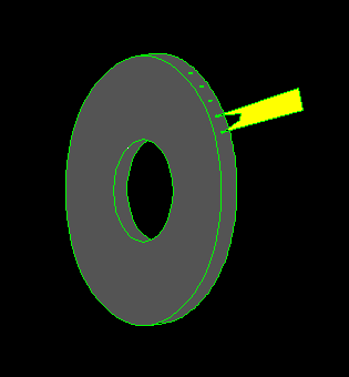
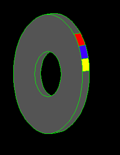
Heat paints are used on the edge of the disc to determine if you are or are not getting enough heat to the brakes. If a certain temperature is reached the paint will change colour permanently. When the disc is checked they can tell the maximum temperature the disc reached. As I understand it this is only used during practice and qualifying. Check references for the colours that go on the disc.
PAINT STICKERS
These are stickers that they place on the calipers and other parts of the car where they are worried about excessive temperatures. This sticker changes colour permanently as a temperature is reached. There are a variety of manufacturers of these stickers and they have different colours. The most common one appears to be the light blue rectangle with the middle section coloured. To make these buy some decal sheets in light blue and yellow. If you want to get fancy also buy some black decal paper.
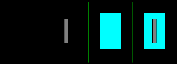
You will then cut up the decal sheet into various strips. 1. Tick marks made out of decal paper, 2. a small long yellow rectangle 3.a light blue rectangle 4. The finished item with layered decals. If you are using black you will be trying to make tick marks If using decal paper you will have to assemble the decals on the model. I don't know how successful you can be assembling the yellow and black decals on the blue one and then apply it to your model. Instead of black decal you can use a technical pen. A second method of making these temperature stickers is to use rub on transfers. If you can find some the right colours you can cut these out and then assemble them on clear decal film. When finished they can be cut out and applied to your model.
CALIPERS MANUFACTURERS DECAL LOGOS
This method is slightly dependent on the ability to find rub on transfers with the same lettering as on the calipers. Using the same method above these logos can be made and placed onto the calipers.
DETAIL LEVEL 3 - INSANE
This method applies to brake systems where the disc and caliper are one piece items. It should be noted that this isn't the easiest of projects, as surgery is needed on quite a few different parts.
DISK BRAKES
Most of the time the kit supplied brake disk is not used and an aftermarket one used. There are a variety of aftermarket Photo Etched ones for solid, and drilled disk brakes (1:24 - 1:20). Let me tell you these look very impressive on the kit, especially the drilled ones. They can get a bit pricey so don't use them on every model you do. These look best on cars with steel type discs. For carbon fiber ones they will have to be painted over which would be a waste. If they are carbon fiber scratch building them out of plastic sheet would be a preferred method.
For aftermarket PE discs the mounting point of the kit will usually have to be modified. See Fig 3. It should be noted that the inner hole is usually pretty large and modifications will have to be done to get it mounted to the kit.
To assembly these disks just follow these steps.
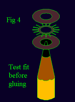
1. Find a pencil or paint handle that you can drop the PE disk brake down onto. This is to make sure they all line up when you glue them. There should be little to no movement in the disks when lined up or there may be problems when you come to glue them together (see Fig 4)
2. Sand one side of the outside disks and both sides of the middle portion. Use 600 or higher grit sandpaper. This will give the glue something to gram onto and produce a stronger bond
3. We will be using CA (super glue) to assemble this system so you don't want to make any errors.
NOTE: If you do make a mistake during construction, don't panic. You should be able to pry the pieces apart. It won't be easy but it can be done. Use an exacto blade and try to slide it between the glued parts. Be very careful you do not cut yourself or damage the part
4. Drop the first disk onto the pencil with the sanded side up. Test fit the middle section to make sure it lines up. Add a small amount of CA glue to the inner part of the disk. Spread it around to cover most of the disk. If you did the first step correctly you should be able to drop the middle portion and it will fall smack in the middle.
5. After some drying time do the same thing with the final disk
6. If there is some CA glue marks after it has dried you can gently scrape it off with a toothpick or your fingernail. Do not use an exacto blade since this can damage the PE part.
SCRATCHBUILT DISCS
Now you ask, can you make your own discs? The answer is yes but it isn't the easiest thing to do. For carbonfiber disc it is recommended that youuse sheet styrene as your scratchbuilding material. See also the above vented disc section for adding realism to your scratch built part.
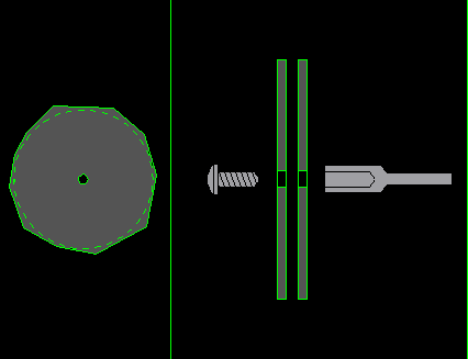
This section applies to larger scales (ie 1:12 & 1:8) steel discs. Your best bet is to use something like sheet aluminum since this can be polished up nicely. Cut the disc to the approximate circular shape (see above left). Drill a hole in the middle so it can fit on an arbor. (a thing for mounting cutoff wheels for your dremel tool)(see above right) This will allow you to chuck it into a drill or Dremel tool. Spinning the disc you can slowly file the disc into the desired circle diameter. You can also polish the surface of the disc with some sandpaper (600-1000 grit) to shine it up and to give it a used look. To make these discs drilled out take the kit part and drill out the holes. Place this over your new disc and made slight marks where you are going to be drilling. I have to warn you that this can take a long time and be very boring.
Use this method only if you cannot get aftermarket parts or can not find aftermarket parts in the size you want. If you also want them vented be prepared for a ton of work. Look at the diagrams for the aftermarket parts and try and reproduce them in sheet aluminum.
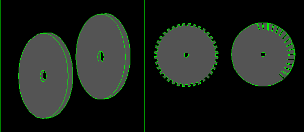
The diagram above left shows two completed discs. Two at a time should be made so they are exactly the same. The diagram at the right shows two methods of making your disc vented. The sample at the left is similar to what is done in the aftermarket kits. The method on the right is individual vents are cut from sheet aluminum and glued to one side of the disc. Each method is very time consuming and I have to admit I haven't had much success with the method on the right. The hard part is trying to get the slots lined up evenly so it doesn't look sloppy. If you have any ideas I would like to hear them. Keep in mind that I would like to make this using tools that most modellers have access to.
CALIPERS
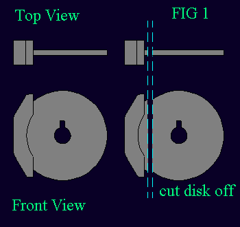
Most kits have lousy calipers and they are molded with the disk. There are some aftermarket calipers in resin and white metal. Detail varies on these objects, they aren't easy to find and they can be pricey. The best (cheapest) solution would be to use the one from the kit or steal one from another kit. The disk will have to be cut off (see Fig 1) and an area has to be gouged out of the caliper to allow clearance for the disk.(see Fig 2.) This is probably the hardest part of the assembly since it is awkward and takes a bit of time to look nice. I usually start off with a cut off wheel in a dremel tool. Clean up with needle files is slow and tedious. Once done you will have to either glue this onto the disk or make a mounting bracket to the wheel hub. I suggest mounting it to the disk.
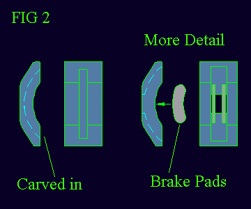
Also check your references as the shape of the caliper from the kit may be off due to moulding limitations.
PLUMBING
This isn't overly complex to do if you have the right materials. To make this look good you have to have some sort of aftermarket AN type fittings or PE nuts. AN fittings are best for 1:12 kit while the PE nuts are good for the 1:20 and 1:24 kits.
The plumbing is usually a line that goes into the caliper. This line is usually flexible. Then a solid line goes from one side of the caliper to the other. The end has some sort of fitting.
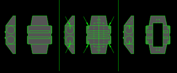
Above is one sample of a brake caliper. There can be slight variations from car to car. In the left diagram is the kit part with a side view and an end view. In the middle diagram the dotted area is the area that is removed so the disc can fit in. the arrows point to common locations that will have to be drilled for various fitting and hoses. The diagram to the right is the finished drilled item. Again check references for exact location of hoses and fittings etc.
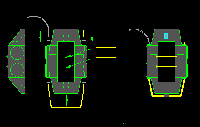
The next step is the addition of the plumbing. (the following corresponds to the above diagram to the left) The top left part is where the brake line goes in. This cab be a flexible hose or braided line. In some cars this may go into the side of the housing. In between the hose and the kit is the AN fitting or PE nut depending on the scale. Adding just the hose itself is OK but personally I think the fitting makes it look a lot better. The bottom line is generally tubing. Use brass rod bent to fit your caliper. Again we have used the AN fittings or PE nuts. The top right fitting is generally a nipple where air can be bled out. I generally use a short length of brass rod and a AN fitting or PE nut. The two rods that go in the middle are also brass rod. They do have a function but right now my mind is a blank. These may vary from manufacturer to manufacturer. Holes will have to be carefully drilled into the kit part to allow these rods to fit in.
The diagram to the right is the finished product
HUBS
Each kit is different so I can only give you a general explanation of how to do this. The hub of the wheel can be cut from the kit part and glued to the new items. You may even want to go all the way and make your wheel removable. See the tip "Uprights" to see how to do this. This way you can take the wheels off to show all the detail you added. This will mean a bit more work, as the wheel also has to be modified.
BRAKE PADS
For the bigger kits (1:20 & 1:12) there is one final area you can add detail, brake pads. Not always easy to see but they are there. Make sure to point this out to your modeling friends (right side of Fig 2)
ROTATING DISCS
I love detail but there are some things I don't want to try at the moment. Trying to get the disc to rotate with the wheel is no easy task. This means you will have to mount the caliper to the hub somehow and your clearances have to be perfect so there is free rotation and no binding. If still interested you should look at one of the 1:12 scale F1 kits to get a better idea of how to do it for the small scales
CONCLUSIONS
Can be frustrating and labour intensive at times but can also add quite a bit to your model.
return to home page http://www.interlog.com/~ask
Send comments, suggestions $$$ etc. to ask@interlog.com