SERENITY - Conversion
This is the method I used to convert the Lightwave lwo file into a AutoCAd DWG format and then used that to create cross sections I used to build my model
Downloaded the Lightwave lwo file from http://www.foundation3d.com(updated Feb 21 2008)
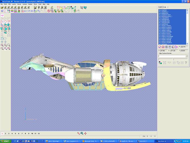
I used the program called AccuTrans 3D V2.9.12 to convert it into a dxf file
Opened it up in AutoCAD LT (the program I have) to convert it into a dwg file (smaller)
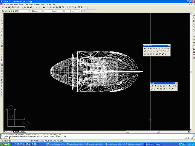
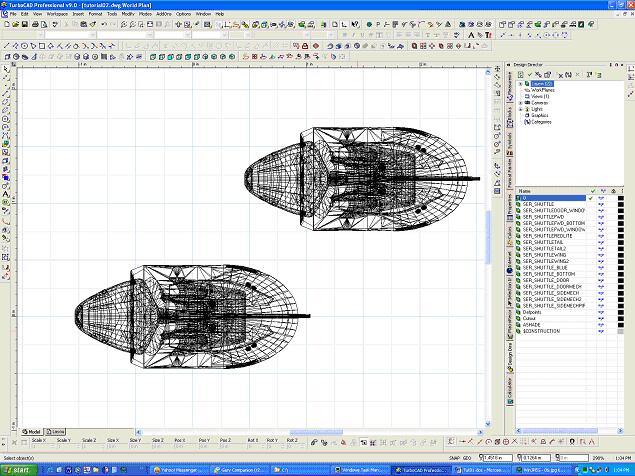
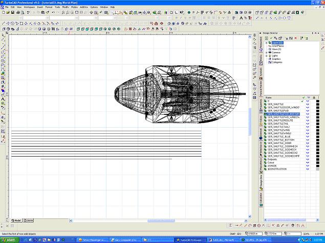
I broke up the file into the various sections to make the files smaller so it is quicker to work with. Here is the top view of the shuttle in AutoCAD LT.
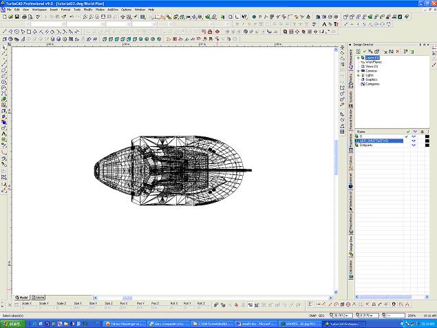
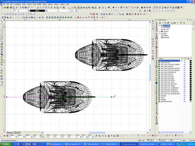
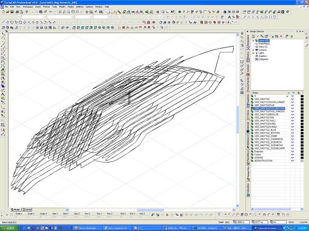
I then opened up the file in TurboCAD V9.0 and loaded up one of the sections(another program I have)(I used the Boolean operation to join up all the parts into one solid)
I placed the image at the 0,0,0 coordinates
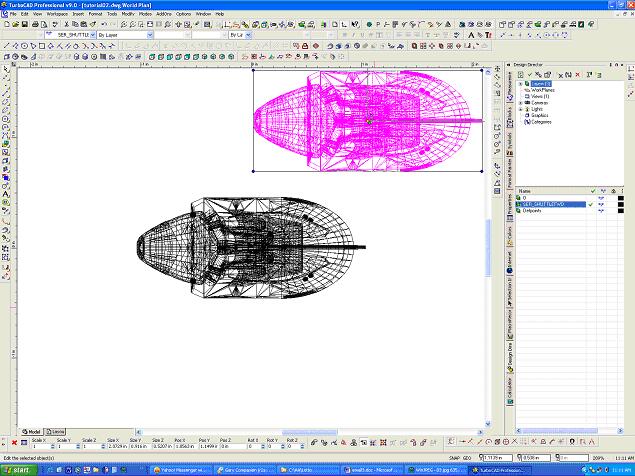
I made a copy of the image and placed it in another section of the file (so there are 2 copies in the file)
I produced a plane. I would make something only 0.001 thick but large enough to cover the entire part. In this case I am making left - right cross section instead of the top -
bottom
place the plane at (0,0,0)
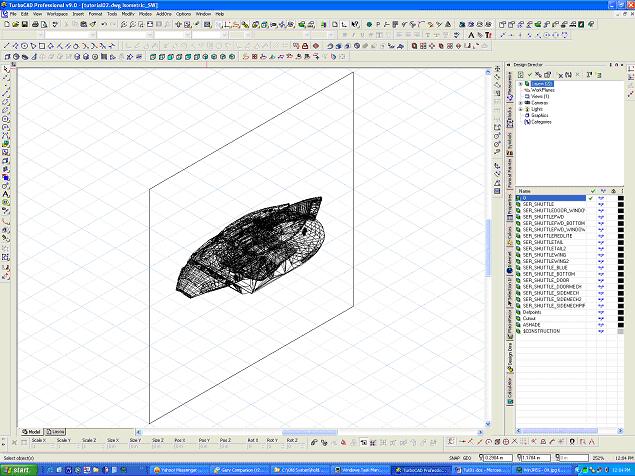
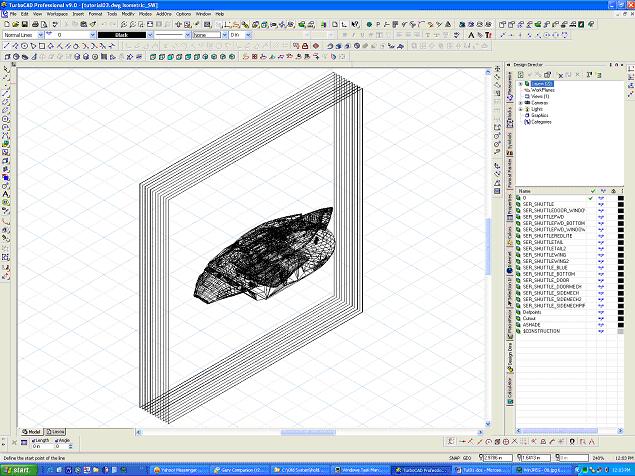
Isometric view with one plane
I make multiple copies of the plane and move them at a set distance from the first one
I made my spacing 0.10 between planes for the shuttle. (spacing will depend on how many planes you want)(a smaller item such as the shuttle . The more planes the better the
detail but the more work will be involved
Isometric view with the copy of the ship removed for clarity
I used the intersection command to pick the first plane and the part. The ship at the upper right is the copy back in it's original place. The very bottom line is the intersection of the first plane and the ship
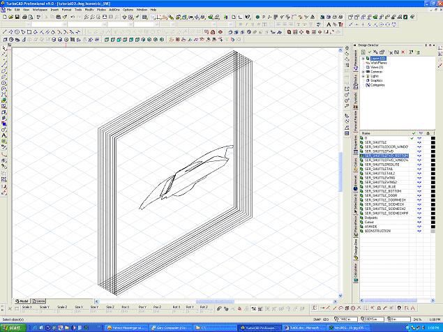
this creates a slice of that part at that location (isometric view)(The copy has been removed for clarity)

I copy the ship again and then move it to location (0,0,0)
Repeat the intersection command with the second plane
Continue to do this until you have a cross section of every plane (since the ship is symmetrical I have to do only half of the ship)
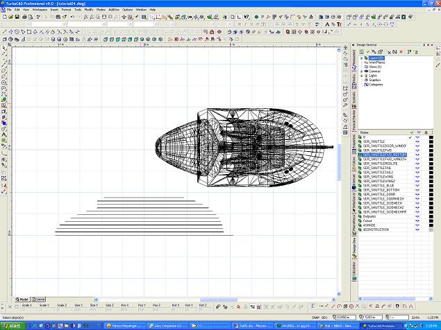
Isometric view with all the intersections and the copy removed. The file is then saved and the program exited
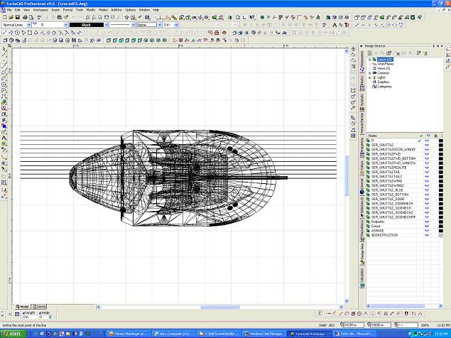
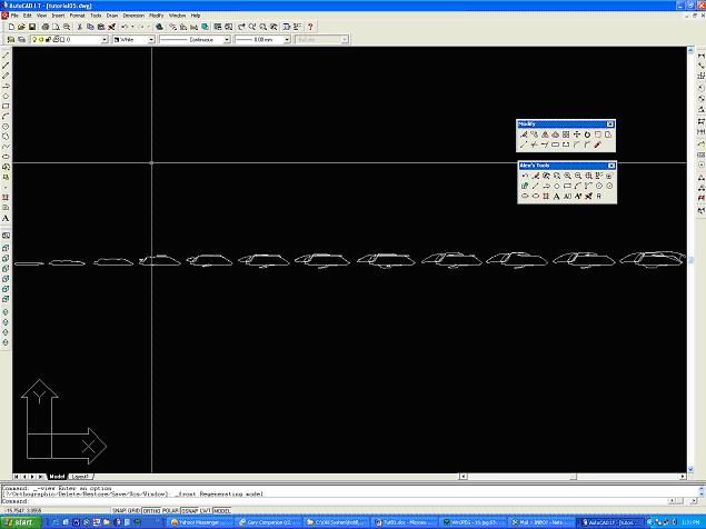
I then opened the finished file in AutoCAD (mainly because I am more familiar with it)(Top view)

I then separated the cross sections horizontally (top view)
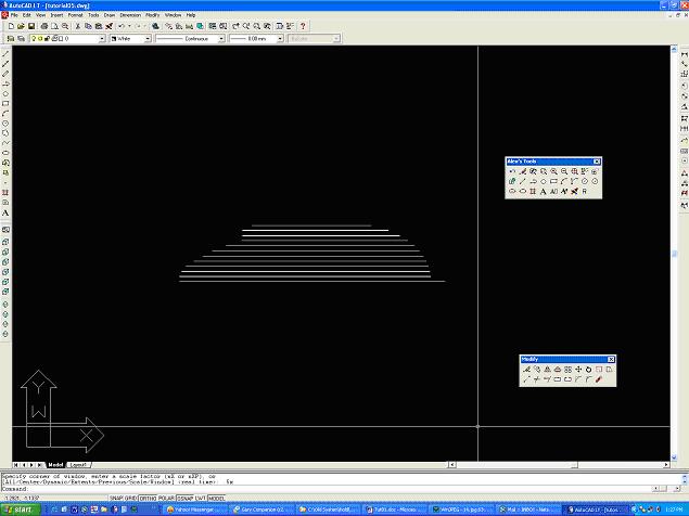
Front view of all the cross sections
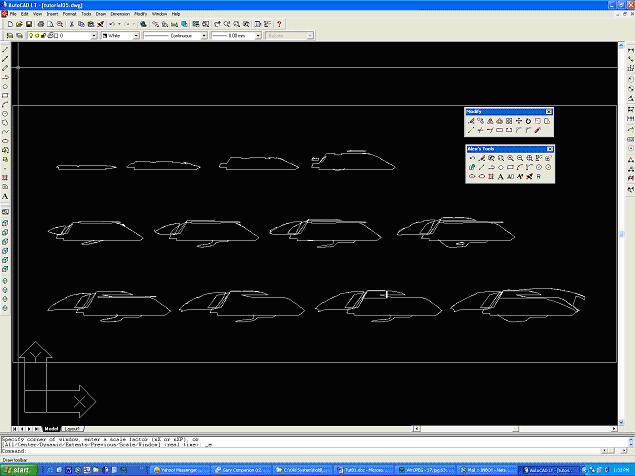
They are rearranged so I could print them out on one sheet. I can then take this 1:1 scale printout and use these as templates to cutout the sections. I make 2 copies so I can cut
out both sides of the ship
This is then repeated with other parts of the ship with different spacing as needed
Note: I used the 2 programs only because those are the ones I have access to. Other programs may do the same thing or be more efficient