Serenity - Sept 17 2007
I am now attempting to add lighting to my model. The main lighting is the rotating engine part. Since I did not want any moving parts I decided to try and replicate this with a chase circuit. I am not good at electronics so I tried to find an existing kit that I could modify. I did find chase circuits but they were designed for standard LEDs (1.5V) and not the super bright ones that I wanted to use (3.2V). Also I wanted to light up multiple LEDs at the same time instead of only one.
I finally settled on a PICAXE 18A which I could program myself with some simple code.
With the PICAXE I could also add more stuff so I add lights to the rear beehive section. Then someone mentioned the side engines so I made plans for that. I have 4 LEDS which will have a random element in them to go on and off to add variety. Finally I decided to add navigation lights as a flashing light.
I can then turn on a switch to turn on the engine lights and another switch to turn on the navigation lights.
At least that is the plan.
0091701.jpg
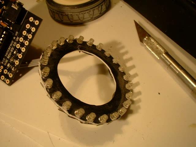
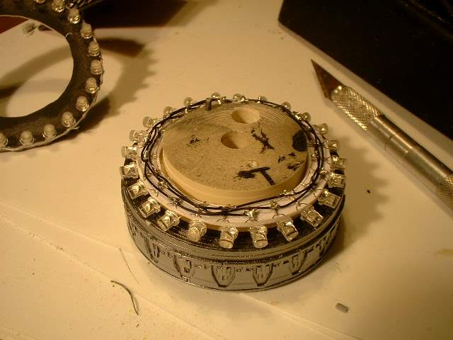
This is the 3rd attempt at the chase circuit. I drew out the pattern in CAD and printed
it out so I knew where to drill the holes for the LEDs. It had too few lights so I added
more until I got 24 LEDs. This was then printed and I drilled the holes and inserted the
LEDs. I then soldered the wires in sets of 3 so that at any one time 8 LEDS will be lit.
I played around with the speed until I got something that looked right. It was smooth enough not to look like a bunch of LEDs. (if I squinted) That point will be important later.
After putting all the LEDs on the template I cut out the inside to fit the modified model part. However the LEDs were too big so I ground down the tops of them. As an added bonus this diffused the light a bit.
Problems started to occur when I tried to install it. It was a bit big and it would look good from one side but the backside was completely blocked off
 0091702.jpg
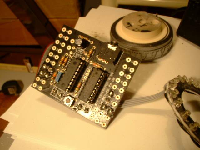
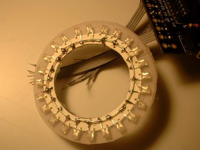
Here is the PICAXE 18A soldered to the first LED board. Behind is the mating kit part that
has been modified to allow the LEDs to fit. I think I used a 22 GA wire for the LEDs and
it was too thick. To save space later on I use 32GA wire.
So farI have only soldered the wires for the LEDs, Power and the switches that I will use later for the engine lights and navigation lights.
 0091703.jpg
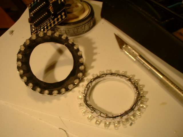
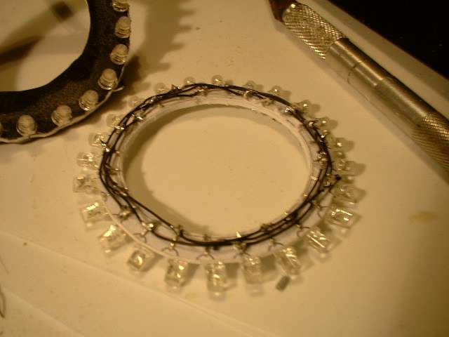
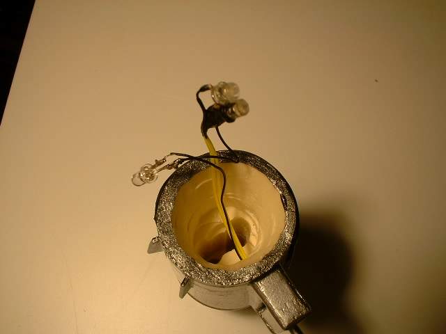
Below is the newer leaner LED board. Instead of 2 holes holding the LED on the board I
have used only one hole and it is perpendicular to the normal direction the LED goes.
Instead of pointing axially to the board it is now radially pointing out so the LED
can be seen on both sides I also had to grind down the side of the LED to save space.
You can also se the 32GA wire used to wire up the LEDs
 0091704.jpg
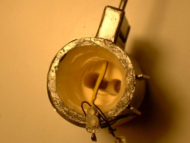
Close up of the crammed conditions
 0091705.jpg
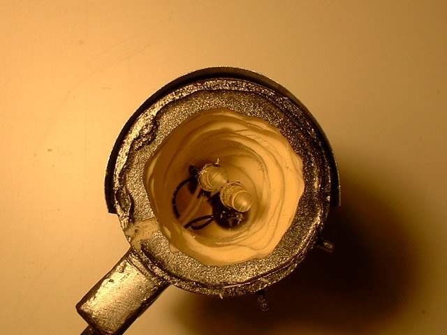
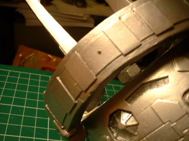
How it looks in relation to the kit part that has been modified to receive the LEDs board.
I have drilled a second hole to allow other LEDs that will light the rear bee hive area
 0091706.jpg
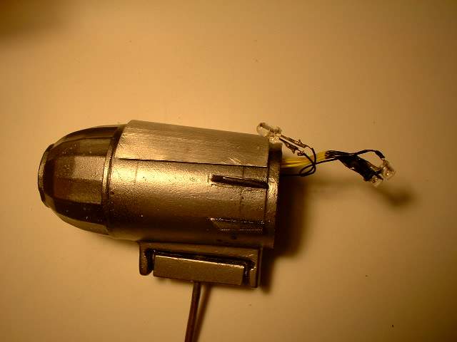
This is the side engines that have been hollowed out to add the LEDs. The 2 to the
right are the rear engine exhaust while the one on the left is for the blinking navigation lights.
Although the formation light should be solid red or green I decided to take some artistic license and make them blink.
 0091707.jpg
Another view showing how deep I had to go with a dremel milling bit and a drill bit
 0091708.jpg
Side view
 0091709.jpg
And one more with the LEDs crammed inside. I will use Fiber optics to bring the light
out to the navigation lights
 0091710.jpg
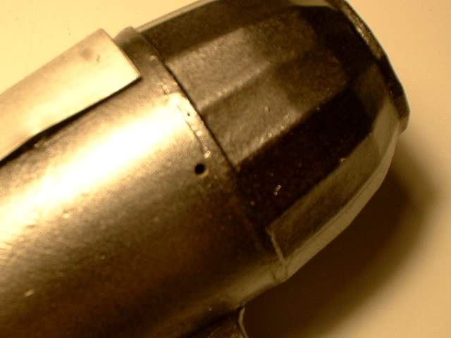
One of the 2 holes on an engine that will be lit fr navigation lights
 0091711.jpg
The other side of the LED chase circuit with the positives all wired up. Different
from most circuit boards where the ground are all common. Also note the clear acrylic
sheet behind it that has been sanded. This was installed to diffuse the light a bit
more as once installed the individual LEDs was a bit obvious.
It is not a concern on this side as it is mostly hidden but the reflection it noticeable.
 0091712.jpg
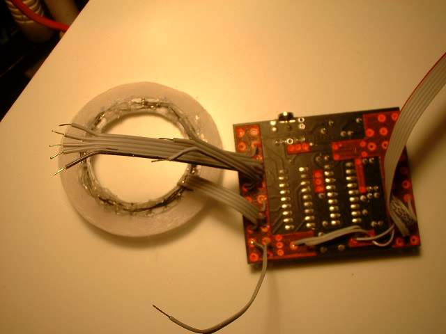
With the PICAXE 18A
 0091713.jpg
The other side with more wiring
 0091714.jpg
The front of the LED chase circuit with the diffusing sheets hot glued on. There are
2 sheets there as it seems to give the best effect. The wire soldered to it is actually
old computer ribbon cable I recycled
 0091715.jpg
Oops a bit fuzzy but I had to add the step in the mounting rod to allow the circuit
board to fit inside the cargo area.
 0091716.jpg
Hole drillde for the navigation light on the main body
 0091717.jpg
And one for the yoke
 0091718.jpg
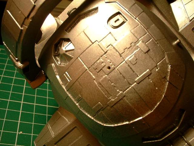
The top side of the yoke
 0091719.jpg
The top side of the main body. Fiber optics will bring th eloght to the top.