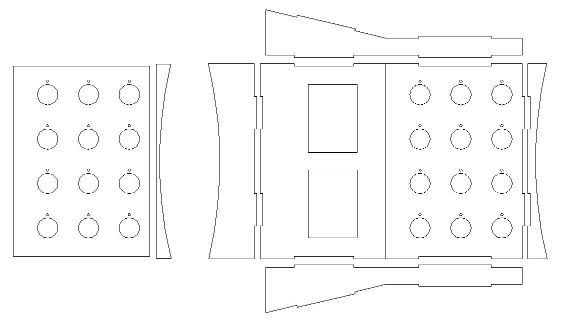
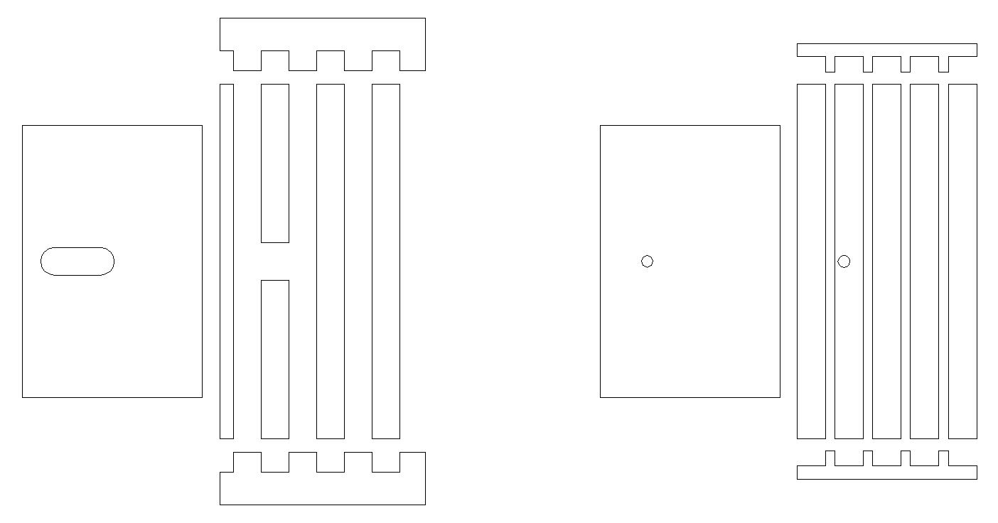
This is a top view of the layout of the parts for assembling the body
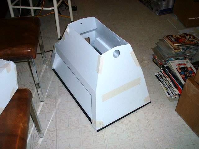
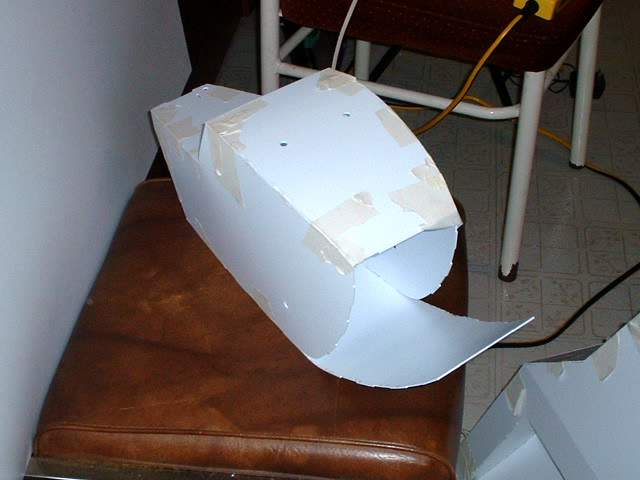
Rear view of the main body components are glued together. It is recommended that all the joints on the inside be reinforced for added strength. I used hot glue.
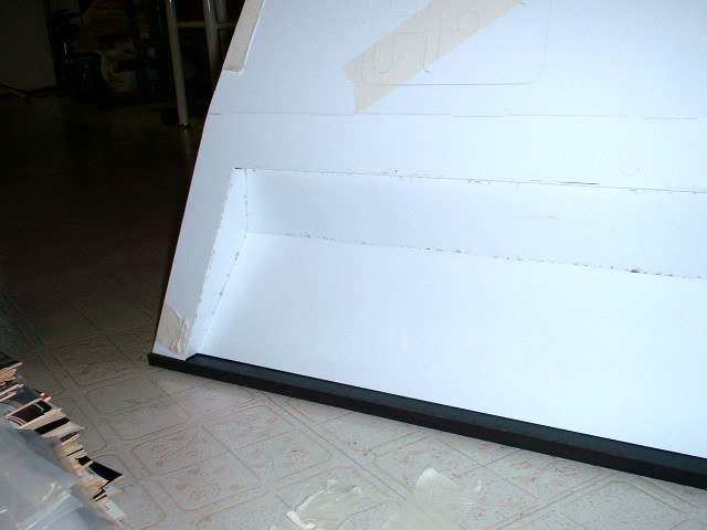
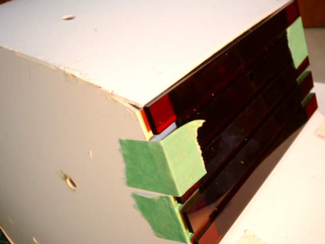
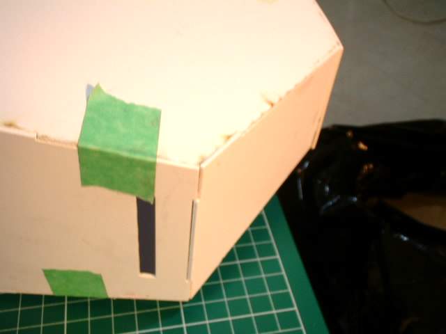
Close up of the side panel
Inside view of the side panel
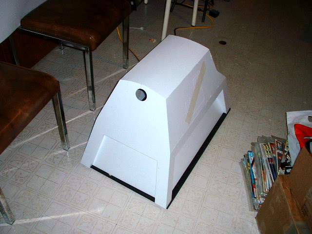
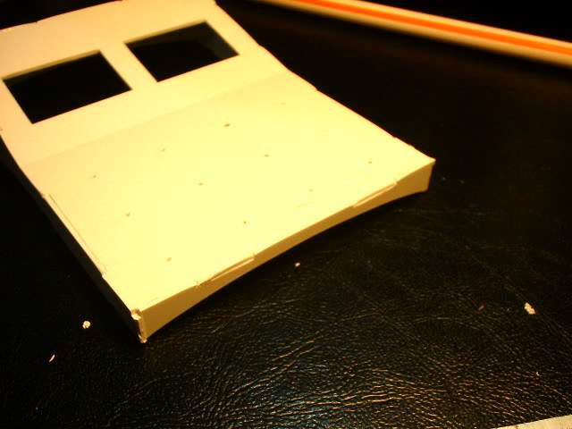
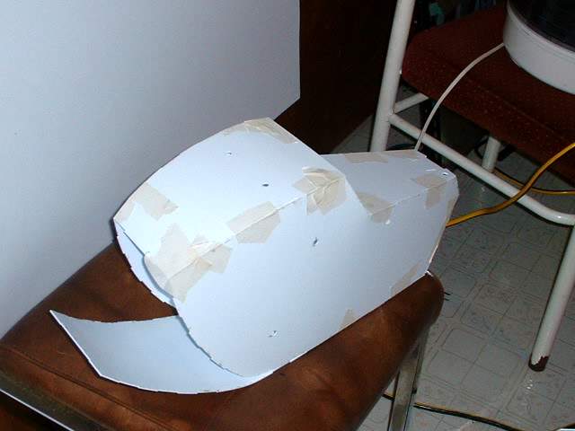
Front view of the main body components put together
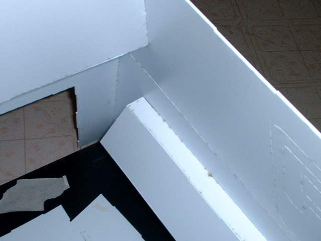
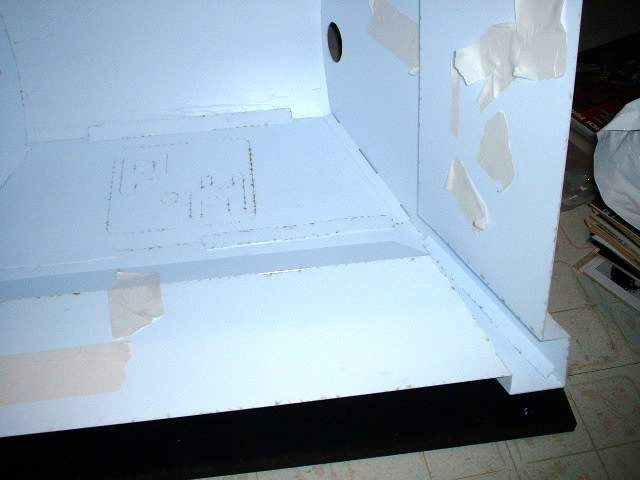
A few close up views of the inside joints
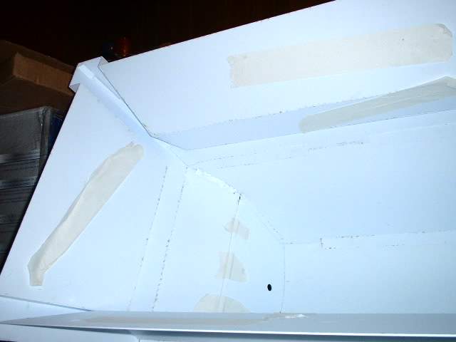
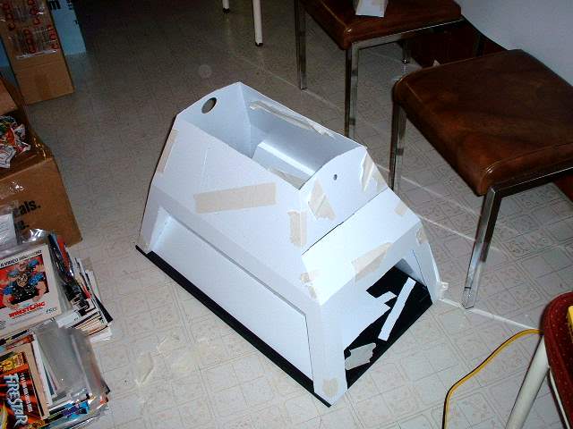
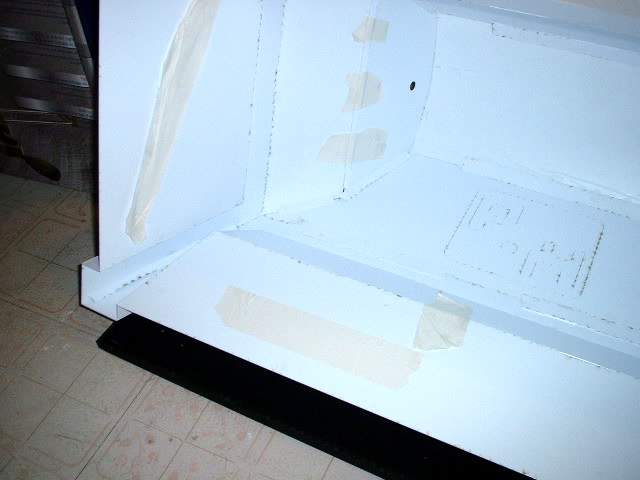
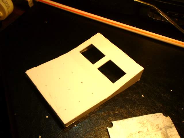
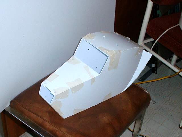
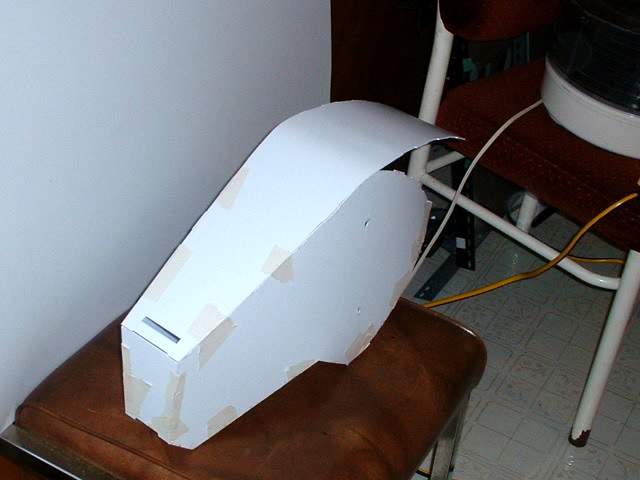
The top as well as the recessed front and rear panels are installed. NOTE: The top goes in only one way and is determined by the keyed slots. This is important so that the slots for mounting the top control box is in the correct location. The top piece is made of thinner material then the side pieces so that it can be easier to bend to shape. Once curved it is strong but not strong enough for someone to sit on it. It is up to the builder to decide if they want to strengthen this area or not.
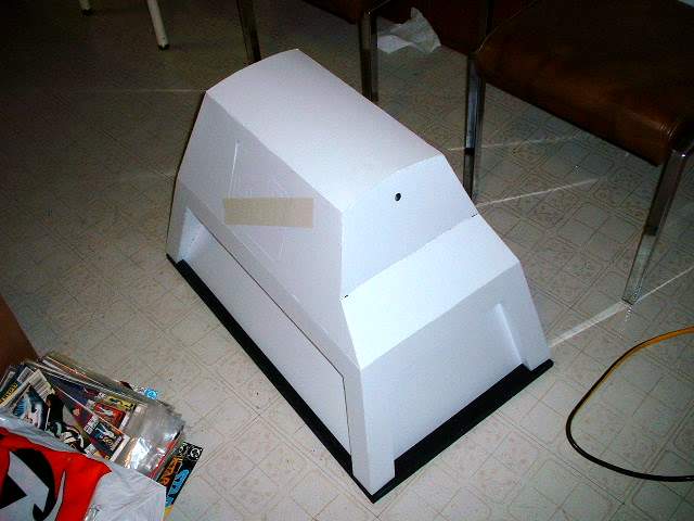
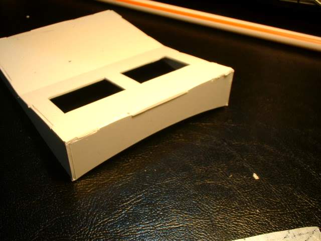
Front view. For added strength what I have done on other projects has been to pour in some expanding foam on the inside. This can give you a fairly hard and rigid shell that can stand up to quite a bit of abuse. Try and use 2 part expanding foam instead of the ones in the spray can.
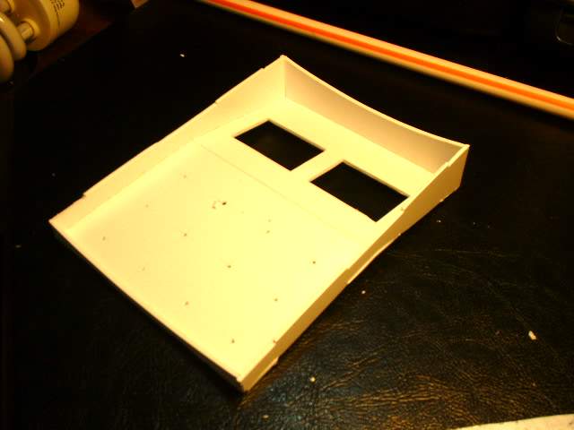
Layout of parts for the top control panel. The parts to the left are extra strengthening parts that go inside. It is up to the builder if they want to use it or not. The switch holes are designed to take the recommended lighted buttons
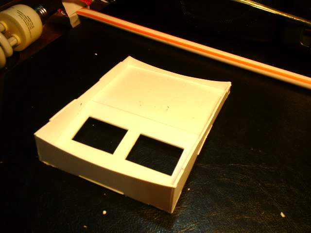
Various views of the control panel assembled. In this prototype the switch holes have not be cut out so that is why it looks slightly different then what is in the kit
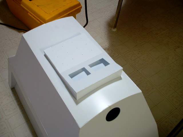
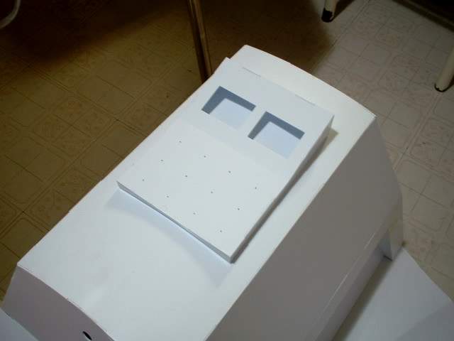
The control panel fits into the slots on the top piece. It is up to the builder to cut an access hole for the wring and switches. This was not included, as it would weaken the material and make gluing and installation a bit trickier.
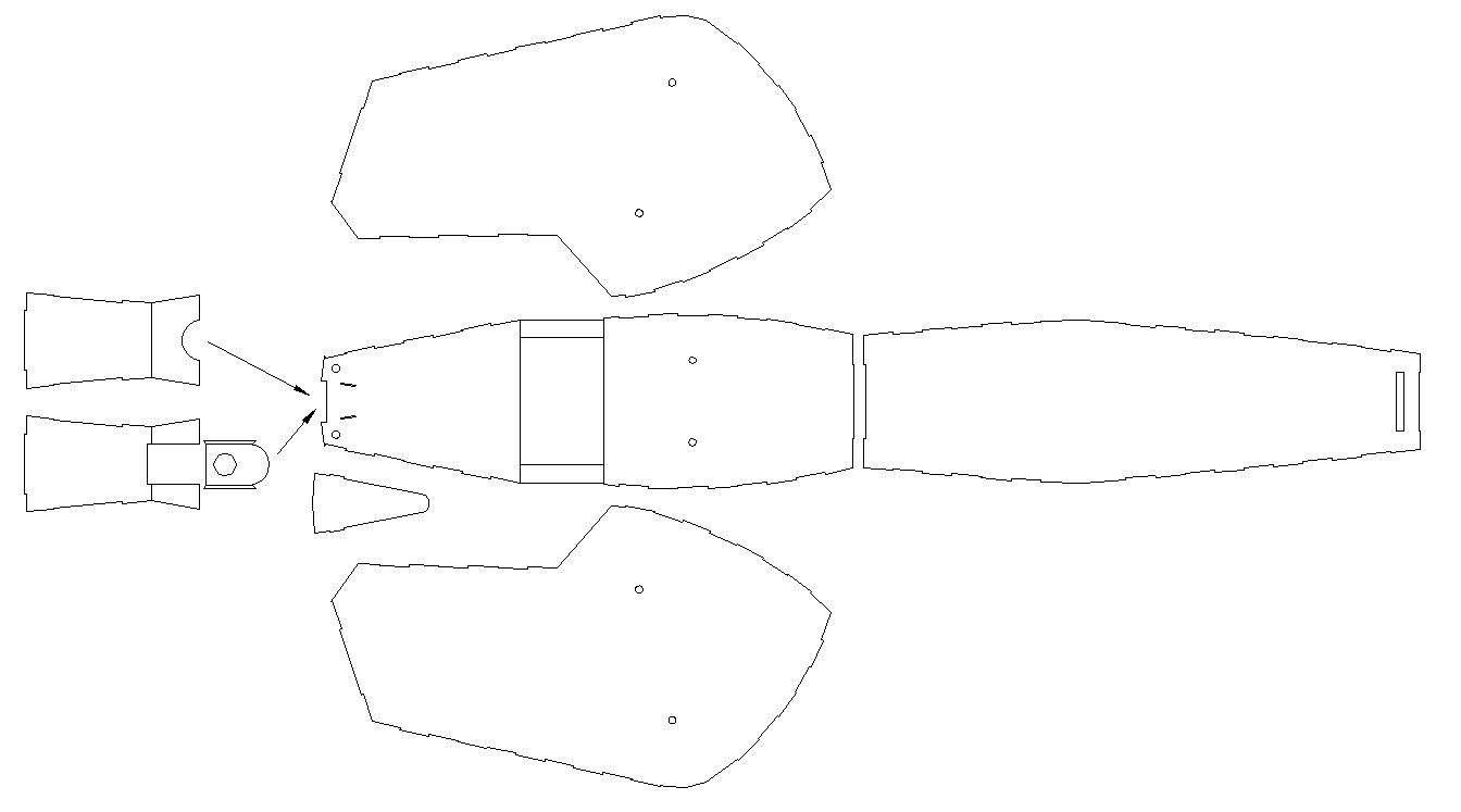
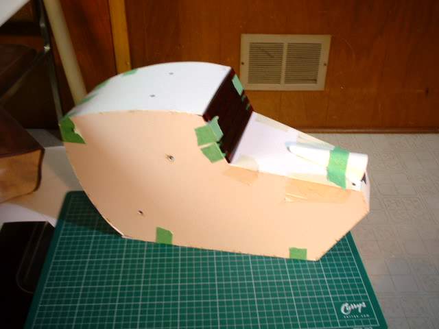
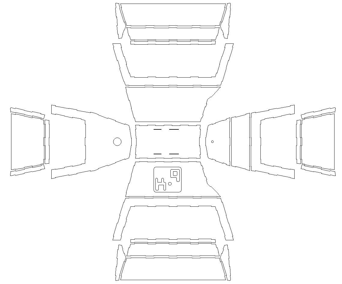
Top view of the head components. To the left are 2 options for the nose area. It is up to the builder to decide which K9 they want to build. As with the top there are no holes to mount ot the neck so that forming the back piece is easier. It is up to the builder to determine where they want to put access hatches
The main components glued together. Except for the back piece. I was trying to decide if I wanted to add an inner structure or not at this point
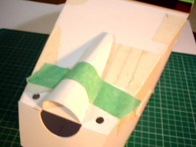
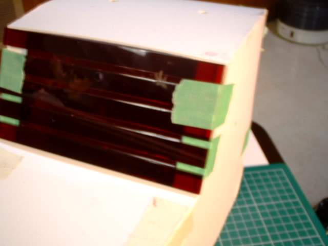
The nose taped on. The nose is slightly taller then it should be and has been corrected for the kit offered to others.
The slot under the nose
There are 2 options for the eyes for K9. Both are included. The top and bottom stepped items are guides to help space the parts evenly during assembly.
Photos of one of the assembled eye