
Tameo 1:43 Ferrari 312T2 1977 WCT77 World Championship Series
May 14th 2000
I bought this kit, took one look inside and was blown away. This kit (like the 312T4 and MP4/6) are unbelievable. I am building this straight out of the box. I will log my progress of the kit as I go along and outline problems and recommendations at each step.
Unfortunately the pictures aren't the best. The engine shots were taken with a 35mm camera and it was still hard to get close detail pictures. The chassis shots were taken with my video camera and a capture card so these are even worse. I hope to be able to borrow a digital camera from work and take some better shots later.

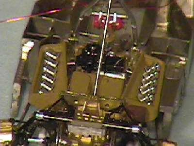
Rear 3/4 view of the engine almost done. The rear wing mount really looks to scale

Rear view of the engine. It is a bit hard to see the details in the engine but there is quite a bit out of the box.

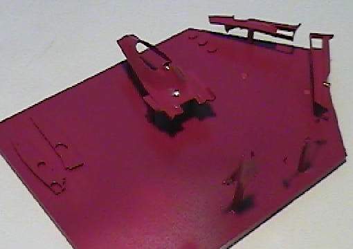
Here is the front of the chassis that is made entirely of photo-etched parts

Top view of the engine. This is all out of the box. The kit does not include wiring so I will probably add this. The wheel hubs look slightly out.

The bottom of the engine. They were a major pain but the exhaust pipes did go in.

The other side of the engine

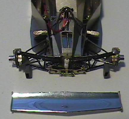
Rear 3/4 shot of the chassis. Almost everything here is photo etched sheet

I have added the two wires to the kit since this is the most obvious omission.

Side View


Step 1
It is recommended that all gold pieces be glued together in steps 1-3 before painting
Pe parts 15,16,17,18,19,20 and 21are nice but they could have been cast into the white metal. We may lose a bit of detail but it did take a bit of time to put these parts on. Save PE parts 22, 23 and 24 for after step 4. If PE part 23 is put on, the suspension part (PE 35) would not go in.
I found that cleanup was needed where the disc brakes would go through
Parts 10 & 5 have a larger and smaller end. Be aware that the smaller end goes towards the gearbox. I accidentally thought the larger end went into part 26. When I found the hole too small I drilled one side out to make it fit.
Look ahead to step 9 to determine what has to be drilled out and what PE brackets can be glued on. This will prevent excessive handling later on
Look ahead to step X where the engine block mates up to the formed chassis. In mine the three white metal mounting pins had quite a bit of flash. This will have to be filed back to get it to fit. Do it now so later on you do not have to handle the almost completed engine while you file these pins. I also found here that the part (box) interferes with the chassis. Filing back the corner that touches the chassis fixes this.
Step 2
I did not glue turned part 4 on until after painting the gold.
Be careful bending part 35. I accidentally bent it in the middle but managed to straighten it out
Step 3
Part 26 would not fit into the two halves. Sanding of the assemblies was required. This created an ugly seam and gap but this would be covered by the disc brake.
I found the PE disc brakes would not fit into the calipers (white metal part 15) To solve this I had to files one side of the disc brake flat until it went in.
When assembling PE part 25 there are two tabs on the front that are supposed to be bent down. This is not shown in the instructions but can be seen in Step 4. This helps in aligning the part. You also have to drill out the holes in the white metal prt (parts 1& 2)
Step 4
Had to bend the shafts slightly (parts 5 & 10) to get them to fit but they were no problem.
It doesn't show in the instructions but holes should be drilled in the white metal to accept the front suspension mounting points.
I made an error and glued PE parts 27 & 30 on the wrong sides. Turns out it doesn't affect the assembly later on. Sure bugs me since I was sure I double checked this when I was putting them on.
Step 5
I found the PE parts 43 & 44 slightly too long. This was no problem as I just cut them to fit. Shocks went of fine
Step 6 & 7
After assembling the engine block parts I would strongly recommend at this point to test fit the exhaust pipes before painting.
I found the exhaust pipes parts 57 & 59 to not fit under parts 56 & 58. This meant I had to modify parts 57 & 59 by cutting the mounting point to the engine block. When it finally fit I then drilled little holes and added new brass rod pins. This required constant test fitting and handling of the engine block. If you already painted the engine block (like I did) you run the risk of wearing the paint off.
Ok I have to admit I made a major error in the above step. I had the left and right exhaust pipes (56 & 58) on the wrong sides, which created fit problems. I was sure I checked the instructions twice. Well the exhaust pipes fit better now but I still think you have to modify parts 57 & 59 to get them to fit
The exhaust pipes take a but of time to clean up but be aware that only the bottom side is seen so the top side does not have to be cleaned 100%. Also make sure the fit to the engine block is flush. Mine had a little flash that produced a very small gap.
With all the fitting and modifying the original paint job was badly chipped. I found trying to install them caused little flakes of white paint to be chipped off. These were touched up after the exhaust pipes were finally installed.
Check to make sure the ends of the exhaust pipes meet the two brackets that hang off the calipers. Also make sure that from the top and side views that the pipes are parallel.
Recommendations:
1. Test fit each individual exhaust pipe to engine block to make sure there is no gap. Modify as needed
2. Test fit the entire side to make sure one fits under the other. Modify as needed
3. Glue the ends of the exhaust on. Some drilling will be required. (after this point you can assemble the gearbox etc to the point where you are ready to install the exhaust pipes)
4. Test fit these to make sure they meet up with the support brackets that are hanging off the calipers. The ends of the exhaust pipes should touch the support bracket and there should be no gaps between the pipes and the engine block. Bend as needed.
5. One satisfied that everything fits then you can paint the exhaust white.
6. Be careful assembling as I found it very easy to chip the paint off.
Step 9
The two assemblies beside step 8 should have been done before step 9. (parts 65,66,67). Here again I made an error and glued the parts on backwards. It only became obvious when I tried to glue it to the engine block. It was nice and glued together so I didn't want to try and pry it apart and risk damaging the PE parts.
I had no problems with parts 68 & 69. A quick test fit here showed the pins did not meet the holes so I cut them off.
Step 10
Parts 88 & 89 were a bit finicky and took a steady hand to glue on. The ends didn't go into the gold part (65,66,67) so I had to open the hole with a pin vice. One also has to be careful to use very little glue or you will get glue all over the place.
The 67 & 68 assembly had a slight fit problem. A little filing on the inside was needed to get it to sit down. Because of the tight fit make sure you test fit and are very sure how it goes in before you apply any glue. Over the next few days I did have these part fall off several times.
Parts 86 & 91 didn't fit in the PE or white metal parts. A little filing needed here
For the intake trumpets I placed them upside down on a flat surface. I then placed the PE parts on tip and glued them on. This assembly was them glued to the white metal parts. Test fit here also as one of them did not sit into their holes. Some cleanup needed
Step 11
The rear wing mounting bracket was very fun to do. No problems here. I realized that I did not drill the hole for part 102. I did not want to risk scrapping off paint so I cut the mounting pin off part 102 and just glued it on.
The assembly with parts 96-100, 103, 104 was a bit trickier as the angle to bend parts 96 & 100 weren't exactly clear. As before I did a slight bend and finalized it when installing parts 103 & 104.
Step 12
No problems encountered here but you have to be wary about part 115. There is a slot on one side that has to be positioned correctly to allow the roll bar to be installed later. Lost part 107 but this was again easy to make
Step 13
Here is where I started to lose parts. I lost part 121 but that was ok since it was easy to scratch. I lost part 125 but for some reason there was a double of this part on the PE sheet. The entire roll bar and fire extinguisher assembly was a bit troublesome for me. Getting those straps on wasn't fun. There was a slight misalignment of part 127. Part 135 should have been installed before part 115
Another hair pulling session has had trying to install parts 133 &134 and the roll cage. The holes in the PE had to be enlarged and the roll bar shape had to be tweaked several times
Step 14-17
No problems here as the instructions are very straightforward. For glue I use various types of CA. For most items I use gap filling CA which doesn't appear to be as strong as the super thin stuff. For the chassis I would have used the super thin stuff but due to circumstances I had to use the gasp filling stuff.
The only problem with the chassis so far has been the seat. It took quite a bit of test fitting before it went in.
Several bends in the chassis are not very clear how far you should bend them. To be safe I did not bend them too much. Later on in the assembly process it becomes clear what they glue to. (parts 143, 144, 145, 148, 150)
When installing parts 147 & 149 into the PE parts make sure they sit flush on the inside. If not the mounting holes on the outside will not work later on.
Up to this point I have dropped 7 parts and lost 2. One of the lost parts for some reason was doubled up on the photo etched sheet so this was no problem. The second item was part of the roll over hoop and I was able to use the extra stuff that was included in the kit. Luck so far.
When separating the PE part from the tree I use an exacto blade against a metal surface. This has worked well for me and I haven't had any parts fly away so far. I also have a small pair of scissors that I have used for PE parts.
Is there a solution to this? I am cursing every time I lose a piece and complain why they can't make them bigger to hold onto, yet I want the accurate detail. I build in various locations but am convinced that these some small parts disappear into a different dimension never to be seen again.
Right now I am using tweezers but I may have to get very fine ones that can let me hold onto the small parts. Actually come to think of it what is keeping me from modifying an existing pair of tweezers to do what I want?