A&A Frame Assembly Page 5
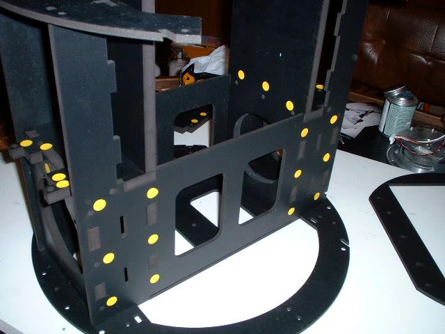
Completing the walk around

Next is the middle ring. The production ring is different as the sides extend to the vertical support

Here is the left side

Here is the right side

Flipped over for the bottom side
The right side

The right side rear

The left side rear

Over all view

This maybe a bit confusing so if you are not sure then go to the next page as it describes the assembly of the styrene boxes. When these are installed onto the arm carrier and the middle ring you will notice the locating tabs will work only one way and this will make it clear which direction is up and down and which holes need to be countersunk


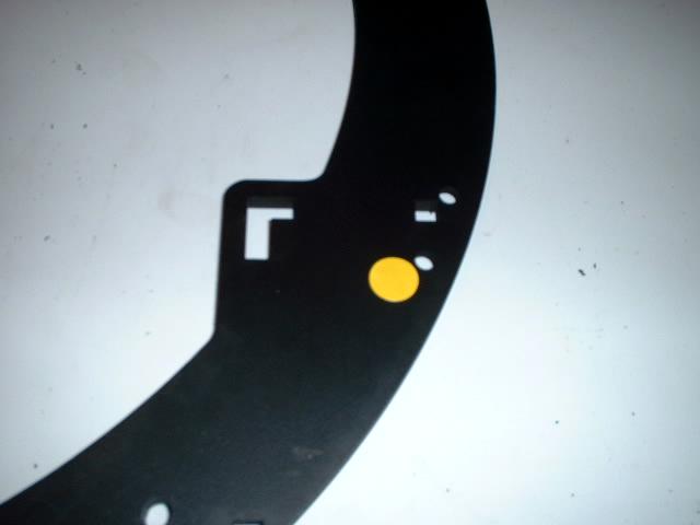
Here is the bottom ring. Note that there is a specific way this ring goes in to line up certain holes. This is the orientation of the ring if the frame was standing right side up
The hole at the top is marked for countersinking. This hole will mount the bottom body ring and the bottom skirt ring. Also notice the square cutout on the bottom of the photo. This is for the vent and power coupling support
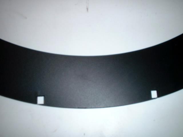
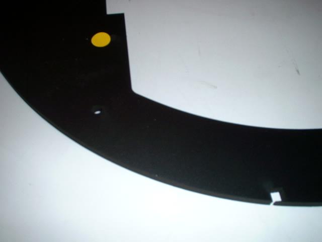
A closer view of the 2 square cutouts

The marked hole and the 2 square cutouts
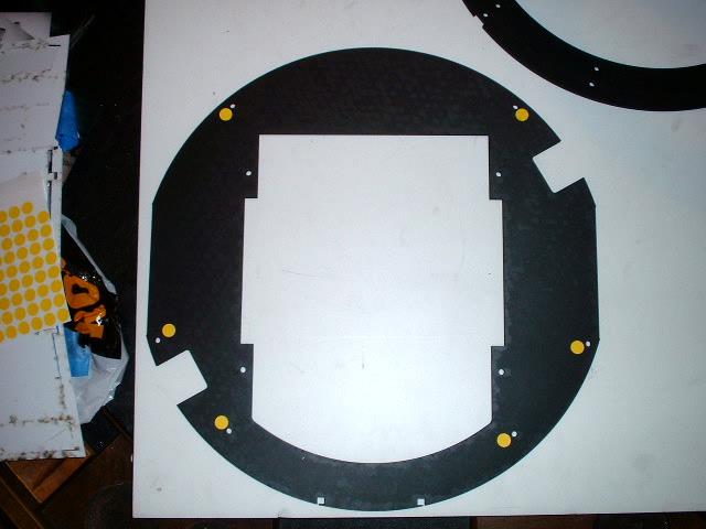
The overall view. BUT the ring has been flipped over to be installed on the inverted frame

The bottom ring and all the holes are countersunk

The next step before we can complete the frame are the styrene boxes. These are boxes located behind the panels.

We are now going to work on the right side door. Not many pieces and some you can use both ways but try and use the good side on the inside as this is what will be seen when the door is open