A&A Frame Assembly Page 1
March 20 2005
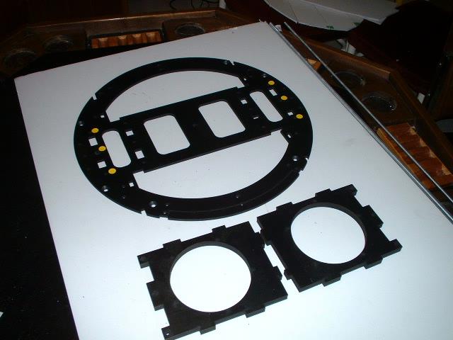
This is the method that I have used to assemble the frame. You can use various hardware that you feel comfortable with. I used 1/4-20 threaded rods and 1 inch long machine screws. I also used No 10 wood screws that are 1-1/2 inch long. It turns out this is a bit long and I needed a few 1 inch screws. This is a step by step identifying the holes that have to be countersunk for the various bolts and screws. One quick way to do this it to try and fi everything together and then identifying the holes that are to be countersunk. You can do this with removable dots as I have used in my sample. The only really part that you may get wrong is the middle ring. This ring makes up the bottom support for the boxes behind the door and the cutouts for these boxes has to be in the correct location to make it fit. If you go to page 4 you can get an idea how to quickly determine which holes are to be countersunk and which side of the part to countersunk.
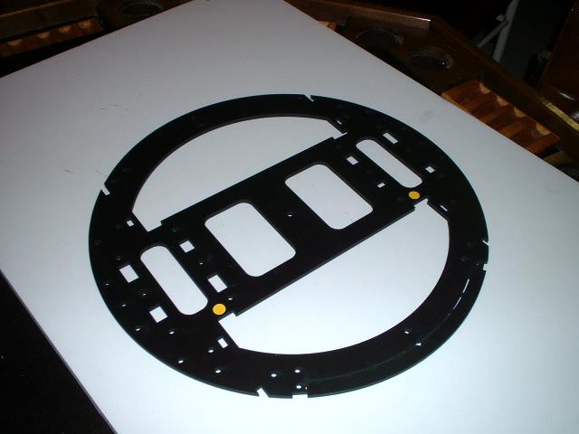
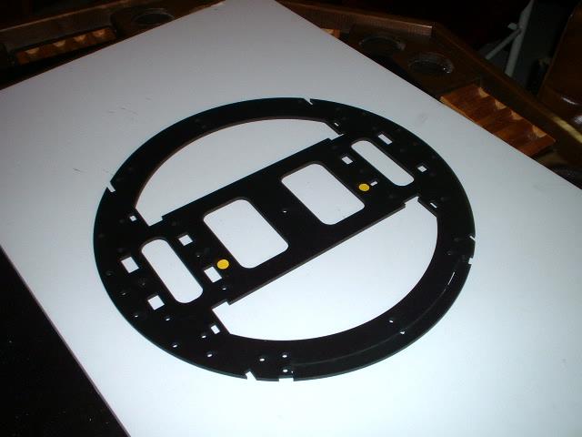
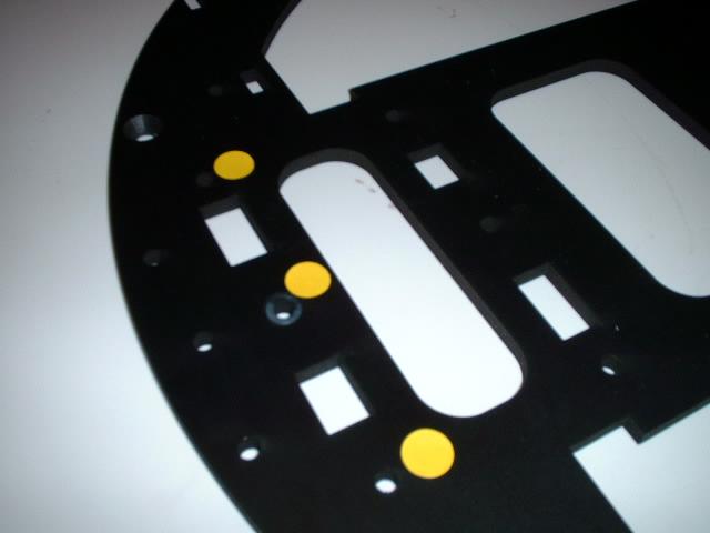
The first step is to countersink the various holes to match the wood screws and machine screws. First off we have to identify which way is up. The yellow dots show where the left and right side is different. Normally the shiny side is the top side.
Other locations to check out
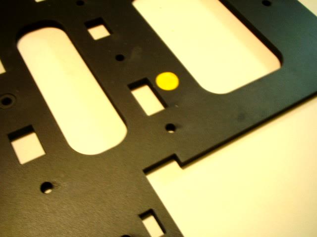
The left side hole. Notice the size. Also below that look at the notch
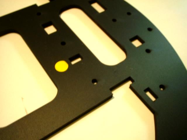
And the corresponding right side hole which is a lot smaller. Also below the notch is slightly longer width wise.
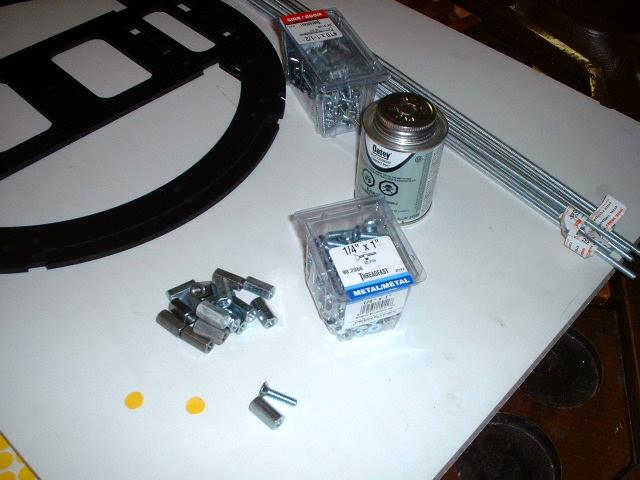
Some of the hardware I am using
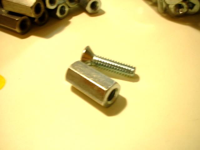
Close up of the machine screw and the coupler
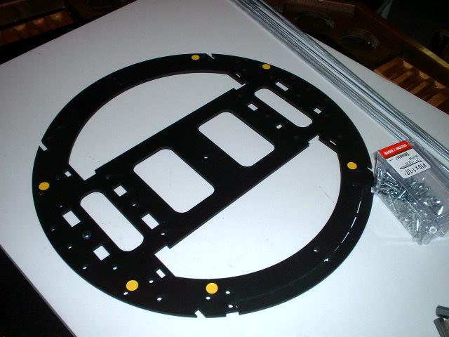
Hole locations marked with yellow dots showing where the machine screws will be for the 1/4 inch threaded rods.
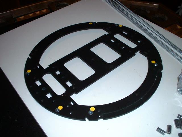
Holes countersunk and with some machine screws installed
Next is to mark the holes to be countersunk for wood screws for the satellite motor brackets
Here are the holes to be countersunk
[ Prev ] [ Next ]