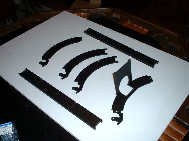
 aaf160.jpg Now it is time to assemble the door. The parts can be flipped left or right to allow the hinge to be on the left or right side. This is a personal preference. I will put my hinge on the right side. The parts are all laid out as they will go together. note that the vertical pieces can be upside down as they look very similar the correct way and upside down. If they are upside down there will be some fit problems with the power coupling holder. Go see the warning at the bottom of the page. Although there are screws holding the assembly together it is flimsy and this door really should be glued together. |
 aaf161.jpg Here is the power coupling holder installed. Note that this is the prototype so ther is only one hole. The produciton versin has a bunch of slots. This allows for the power coupling to be used on an R2 unit or an R7 unit. The lower cutout is for an R2 unit. The higher cutout is for teh R7 unit. Punch out the desired hole |
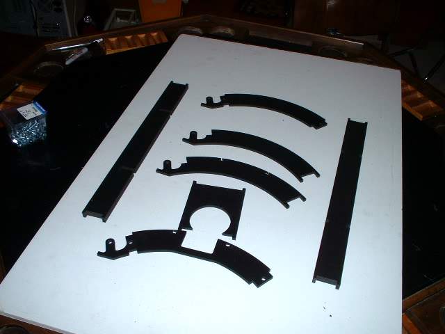 aaf162.jpg Hey lets start again from another angle |
 aaf163.jpg Power coupling holder installed |
 aaf164.jpg Left side piece. If there is a problem with the fit of the power cpoupling the vertical piece maybe upside down. |
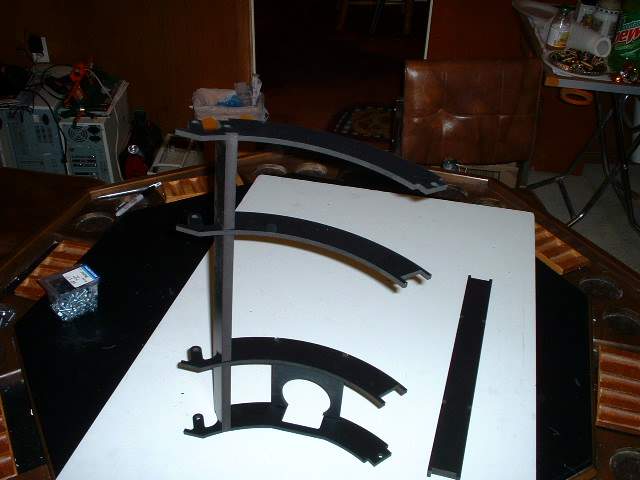
 aaf165.jpg 3rd ring installed |
 aaf166.jpg Mid piece installed to sandwich the holder in place. |
 aaf167.jpg Top ring. Fairly flimsey assembly |
 aaf168.jpg Final vertical piece installed. You can now determine where to put countersinks and where to install screws. |
 aaf169.jpg As stated earlier there is a possibility of installing the two side pieces incorrectly. Here you can see the nothces match the height of the power coupling support bracket |
Page: 1 2 3 4 5 6 7 8 9