 aaf140.jpg I have installed my 1/4-20 bolts into the frame and I took the threaded rod I purchased at a hardware store and measured how much I needed to assemble my frame. I then took a dremel tool witha cut off wheel and cut the threaded rod to the length I needed. I made it slightly shorter then the length so I had a little play. Later on I will use nuts to tighten the assembly. I forgot to get lock washers but these can also be used to lock the rods in place. You will need 4 long rods, 3 shorter rods and 2 really short ones. The length will depend on the machine bolts you buy. |
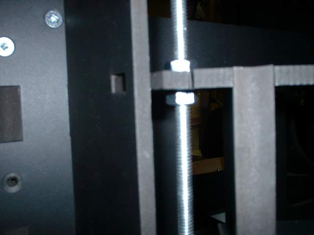
 aaf141.jpg Here you can see how I am threading the rod through the frame and adding nuts as I go along. The nuts will lock the coupler in place as well as position the rings. This adds even more rigidity to teh frame. |
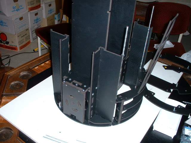
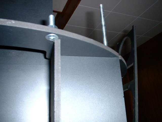
 aaf142.jpg The completed assembly. In this case the threaded rod is tightened into the coupler so a locking nut is not needed here. One will be needed at the top. |
 aaf143.jpg A close up of the bottom corss piece of the arm carrier and the nuts on the two sides of the piece to lock it in place. |
 aaf144.jpg Same idea as above with the middle ring. |
 aaf145.jpg During assembly I noticed a slight fit problem. This problem depends on the size of the machine screw you use. I will now zoom in to show you where I had the problem |
 aaf146.jpg You can sort of see where I had to grind a bit of the frame away |
 aaf147.jpg And there is where I had to do a bit of grinding to get a machne screw to install |
 aaf148.jpg Top side if the area I had a problem with |
 aaf149.jpg Underside and you can see the slight overlap of the machine screw and the frame wall. |
Page: 1 2 3 4 5 6 7 8 9