A&A Frame Assembly Page 11

Another view
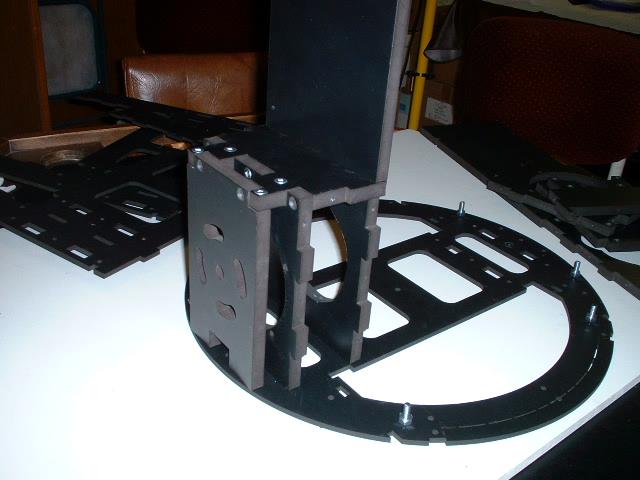
The final piece of this puzzle is the JAG stop. These things are handed. The slots go in one specific direction. How you install it depends on how you mount the legs to the motors. These parts are to be removable to allow the motors to be removed if necessary. For this reason the JAG stop should not be glued in.

Here is the other side assembled

Again the JAG stop to be installed

The rear plate is now installed

The front plate installed
Here we are reassembling the arm carriers. Again this is the prototype so the assembly is different from the production version

All assembled together

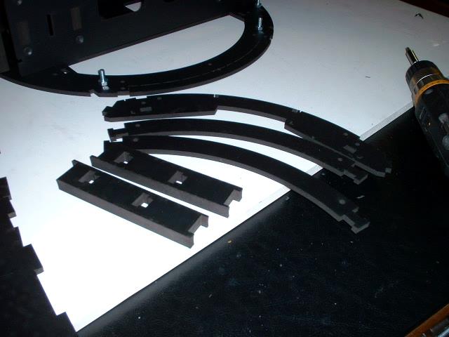
Here is the locations where this frame is different from the production version. Here the cross pieces have a T slot that pops into the vertical piece and drops in place. The problem was that there is no positive system of keeping the parts locked in place. This has been changed so that the cross pieces have a hole in the end and a 1/2 inch piece is placed between the two cross pieces and screws hold it together.

Another view of the area that has been changed for the production frame.
[ Prev ] [ Next ]