99 Days Left Until C3
Jan 11 2005
A lot of this was done before Jan 11 but I thought I would include the pictures to update you on where I am on this project. I have to get this droid finished for C3. Crunch time as there s only 99 days left. To try and make that date I have vowed to do something on one of my droids every day. It can be drilling one hole but everything adds up and that little bit will bring me closer to being finished. Here is the start of a wild ride. Due ot the deadline don't know how often this section will be updated. I will take pictures each day but whe they are posted is another question
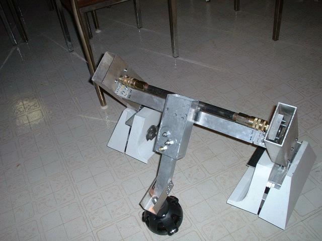
This is my middle leg and partial frame part of my mini
I have used the ball caster for my middle foot as I have in my R2
I had to think of a quick system to disassemble my legs for transport. Mt R2 right now has nuts and bolts and is not bad but it does take time
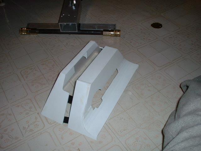
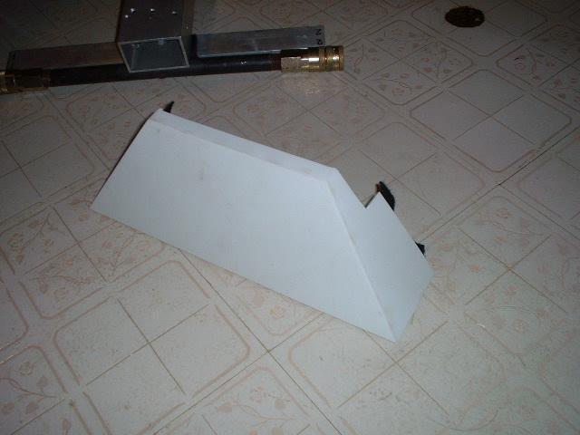
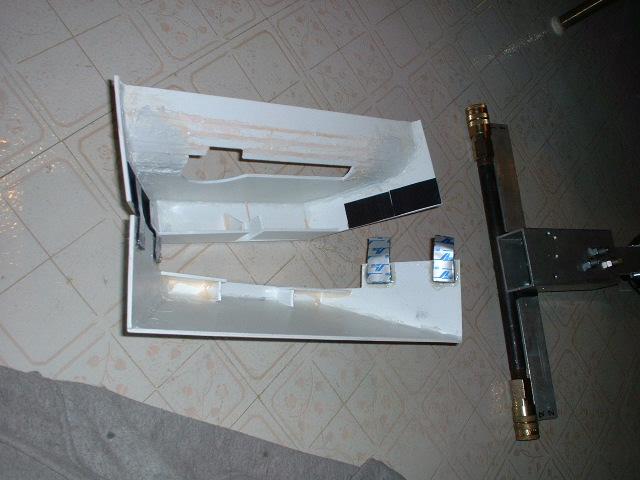
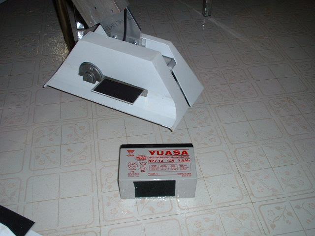
Here are the batter boxes that I have just cut out the area where the motor and battery will sit.
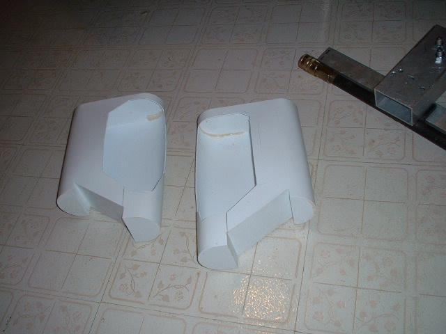
Just in case you missed the previous picture here it s again

A long time ago in a galaxy... no wait. A while ago I used to supply resin battery harness to other members. I got out of the business when the 4th set of moulds started to rip. These are some of the rejects I kept and am using for my mini.
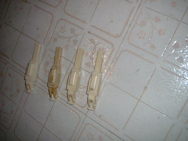
They had to be cut to fit the new style battery box.
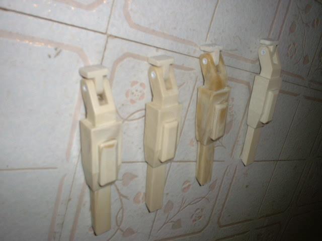
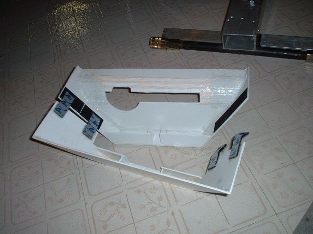
I considered saving time and using only one per side but I wanted to be as faithful as possible to the droid universe. Does that make sense?
Here is what they will sort of look like on the droid
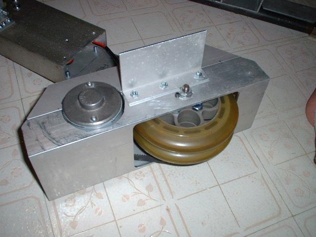
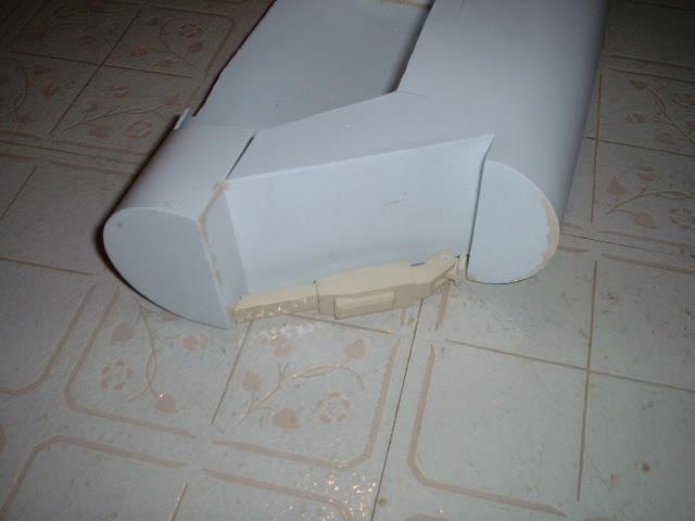
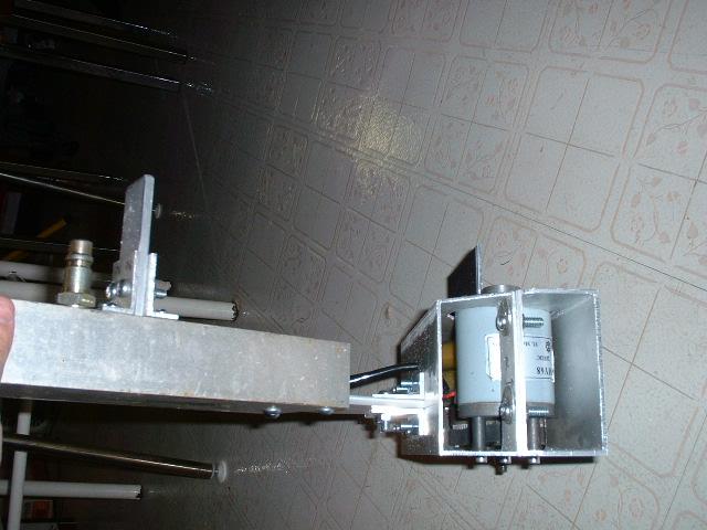
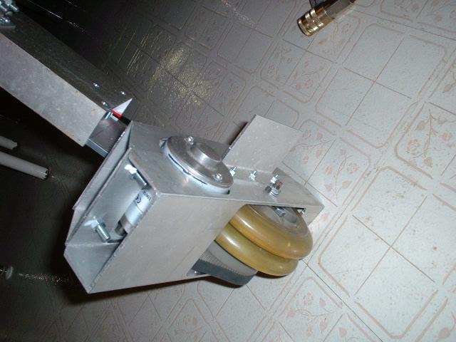
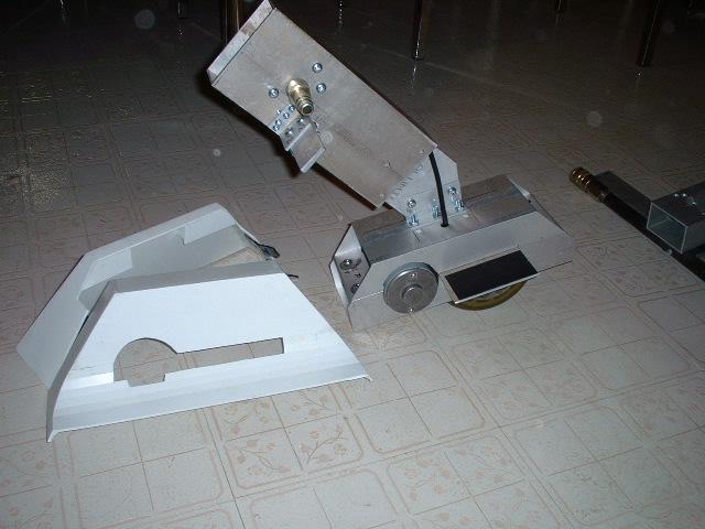
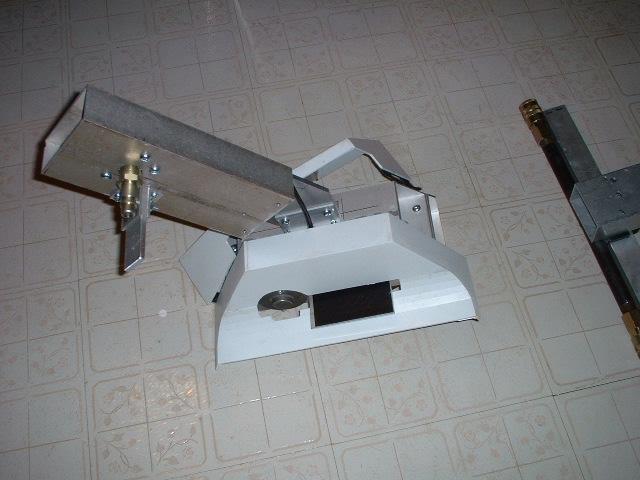
My foot drive system with the battery shelf screwed on and the permanent mounting of the leg body
Leg body is just 2x4 aluminum rectangular tube
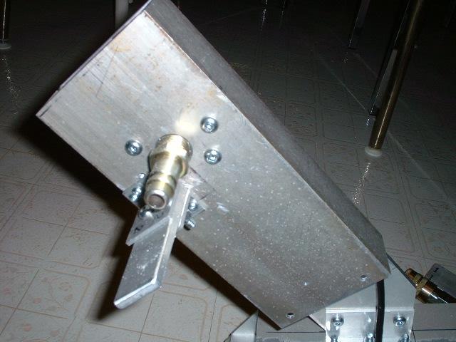
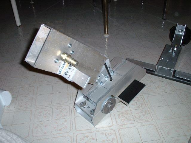
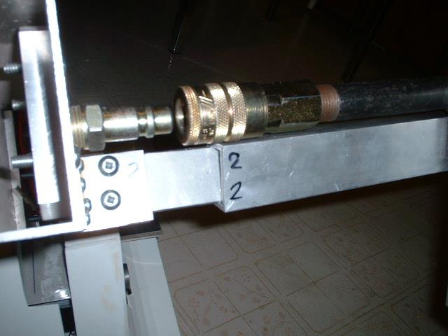
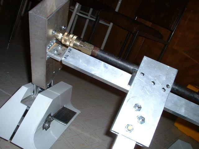
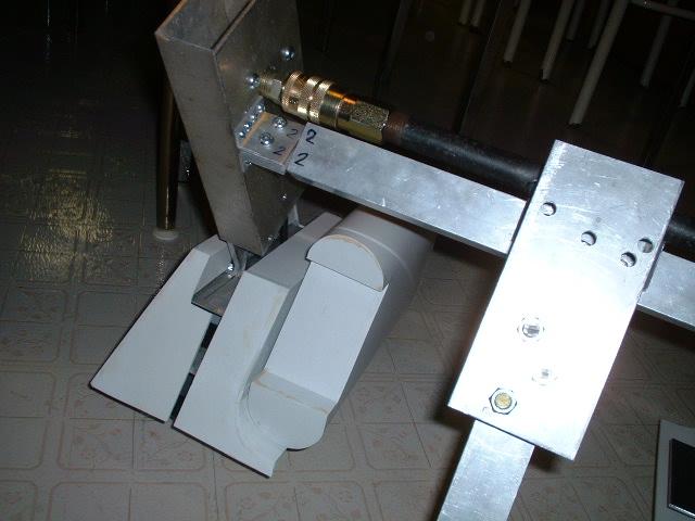
This is how I am attaching and disconnecting the legs from the body. It is a 1/2 inch quick disconnect.
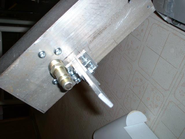
The flat aluminum plate help0s keep the body from pivoting on the quick discnnect
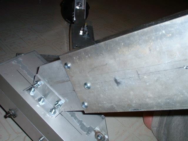
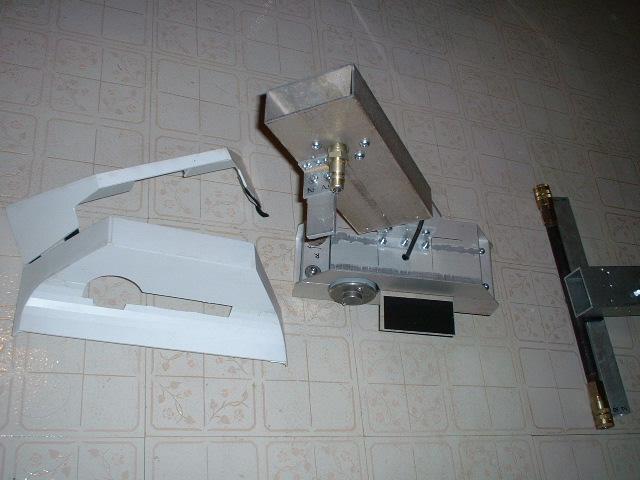
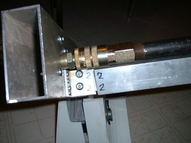
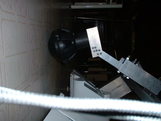
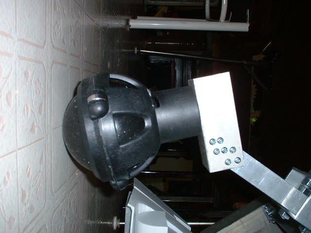
Here is a picture of how the leg is mounted to a aluminum plate and then that is mounted to the drive assembly
Since the droid is in permanent 3 legged mode I do not have to worry about a pivot point
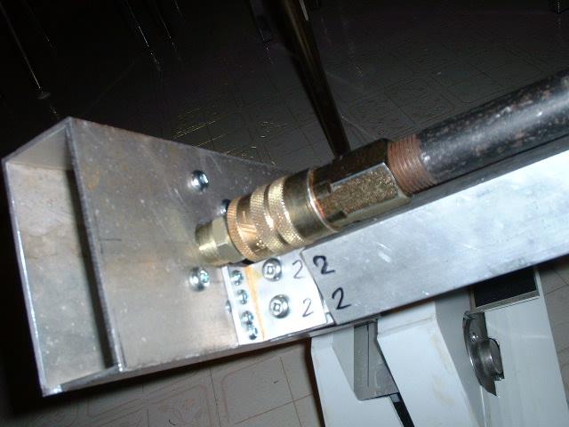
End view
Top view. Most of drive system is covered by the aluminum tubing
The aluminum tubing provides good rigidity. The battery shelf is just aluminum angles bolted to the side of one aluminum tube

Everything is bolted together and can be disassembled if needed
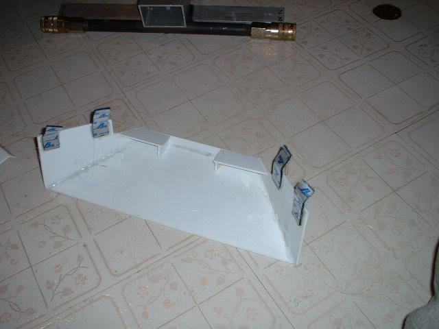
The foot shells were done a long time ago and now I am putting the velcro straps on
This is the same method I am using on my R2 and allows for easy access to the drive system of needed
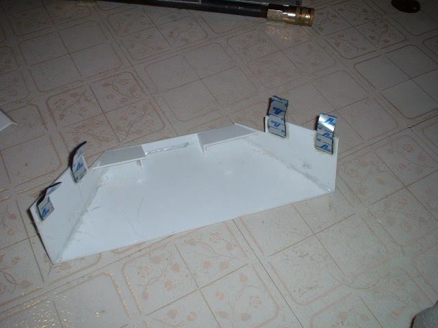
Velcro is hot glued onto the styrene
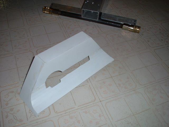
The location of the is mainly for the brass hoses that will come out the front
The other half gets velcro also
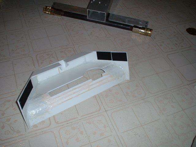
hot glue is your friend
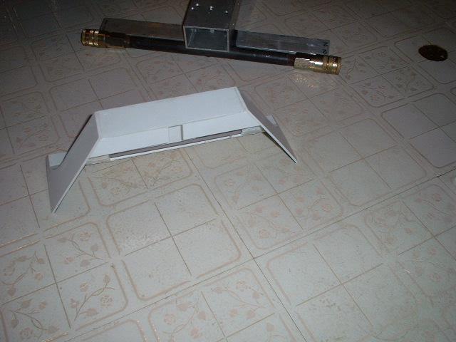
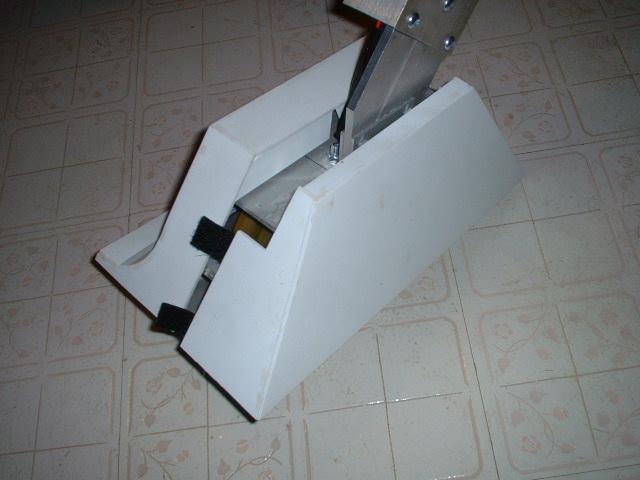
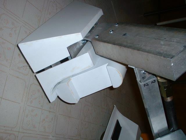
By joining one side the foot shell can be opened up when installed
Open says me
it goes in better this way than the other way due to the battery shelf
Chomp

reverse angle

Closing up
The Velcro tabs are on the outside to show you where they are

All done now ready to assemble frame

Close up of leg
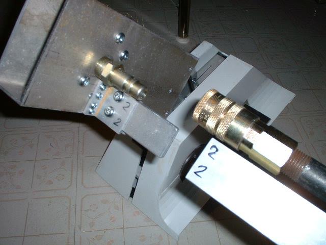
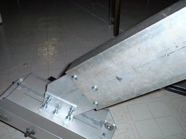
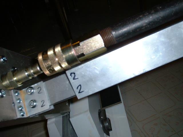
Line things up. I have labeled the ends that have to match up
The rectangular tube on the frame lines up with the flat aluminum plate
Ready to clip in
All done in a few seconds
Another angle
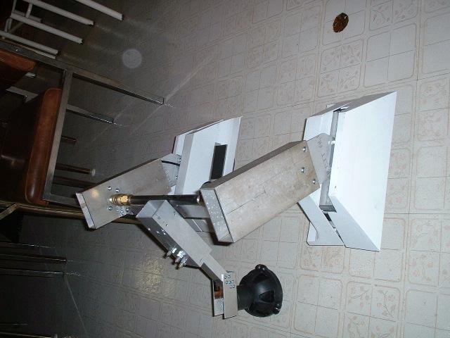
Pan out view
Frame assembled
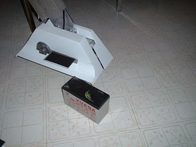
Battery ready to go on. There is Velcro on the top of the shelf to hold the battery in place
See I told you. I wouldn't lie
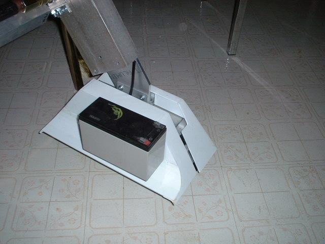
Battery in place. There is a small gap between the battery and foot shell

This allows the battery box to slide in.
Nothing is holding the battery box there but the battery.
I guess I could add some velcro tabs but why when this works
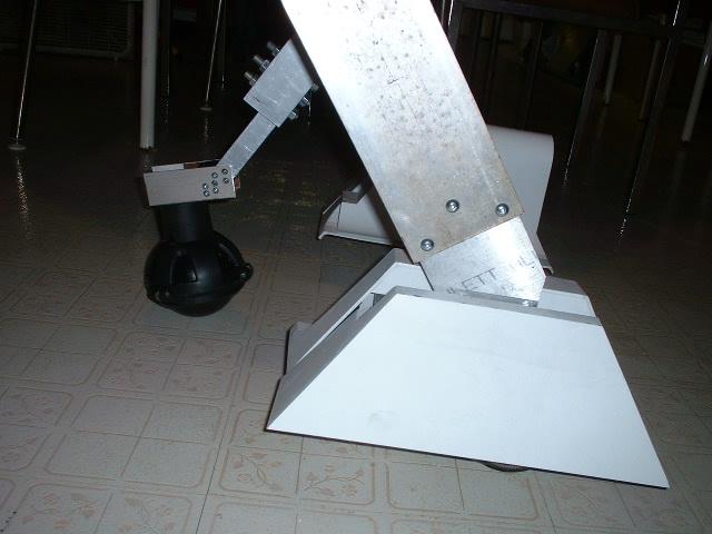
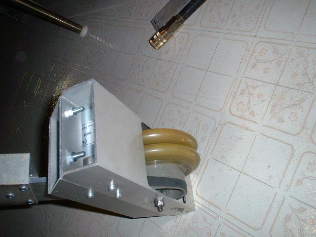
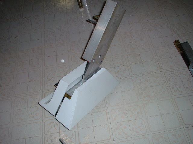
Side view trying to show the angle of the ball caster
it is not straight vertical but is angled slightly backwards. This was done to hopefully redirect the loads an forces so that the ball caster will go over obstacles easier.