A&A Data Port and Charging Bay
Here is the A&A Power Port kit. The parts are made of styrene so the appropriate glue should be used to assemble the parts.
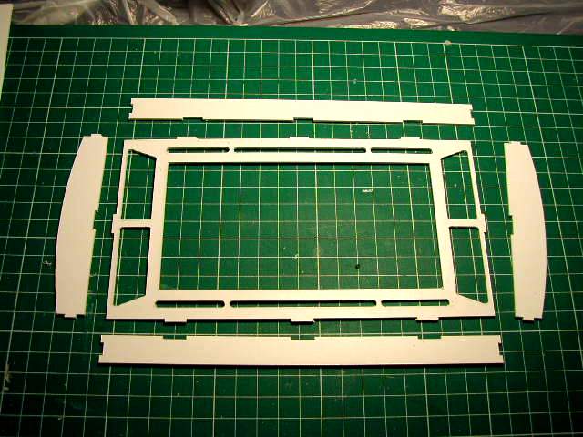
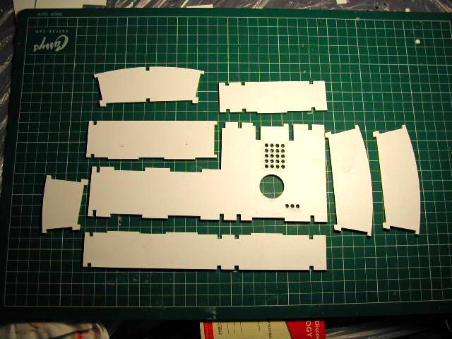
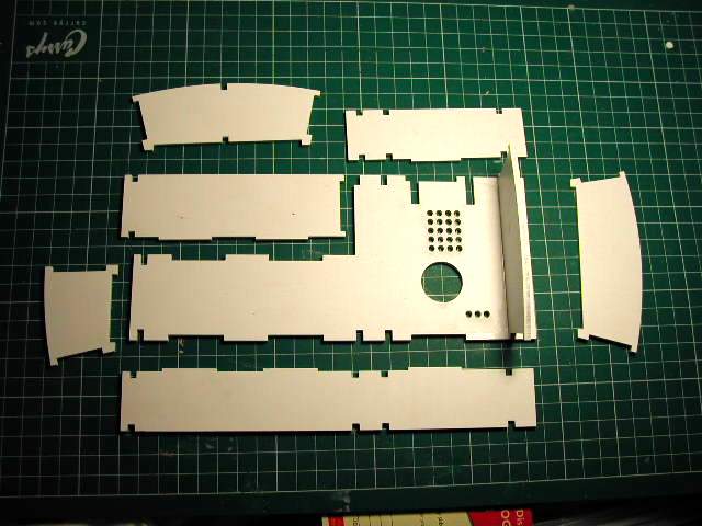
These are the outer enclosure parts laid out ready to be assembled
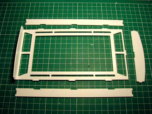
Left wall glued on
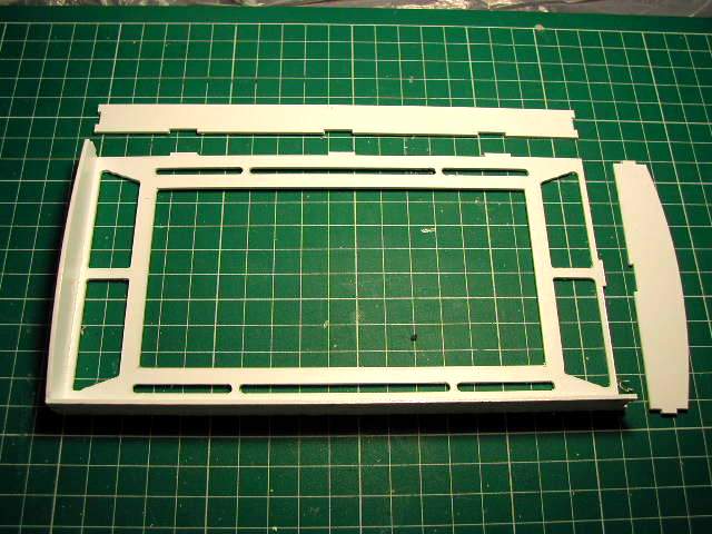
Bottom wall glued on
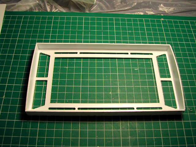
The rest of the walls glued on

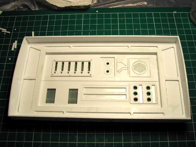
Next is the backing plate. If you want to paint the parts now before assembly it is up to you. The left part would be painted white and the left part would be painted black. The other option is to assemble the parts and mask and paint the item later
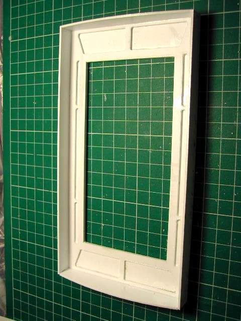
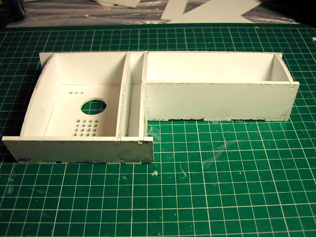
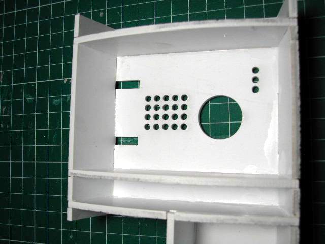
Here is the backing plate glued on. References show that the recessed areas are black and the rest of the enclosure is white
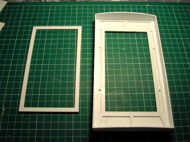
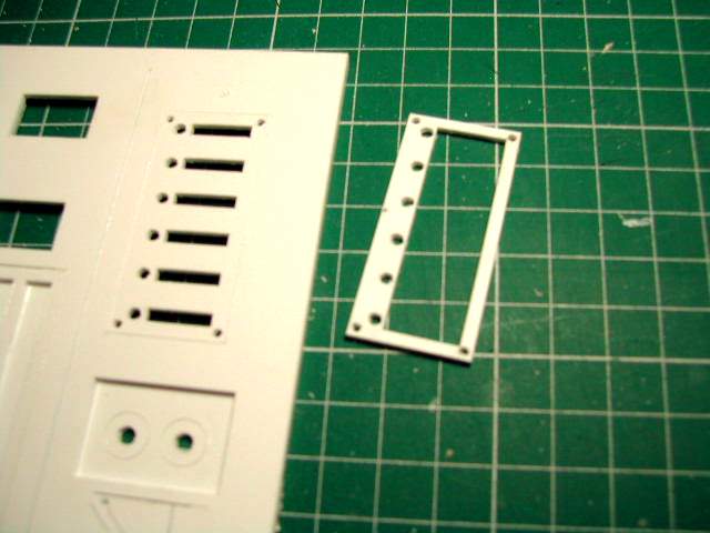
Next to be glued to the back is the small frame
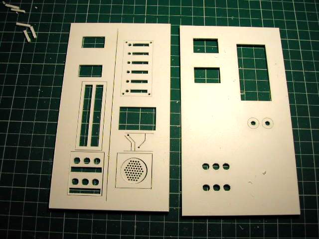
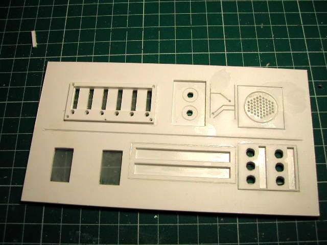
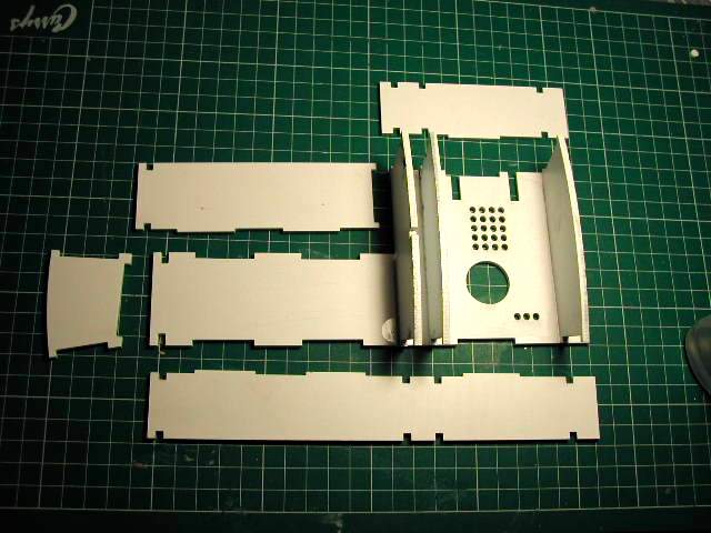
Next we glue together these 2 parts. Note that the panel to the left has a lot of loose parts.
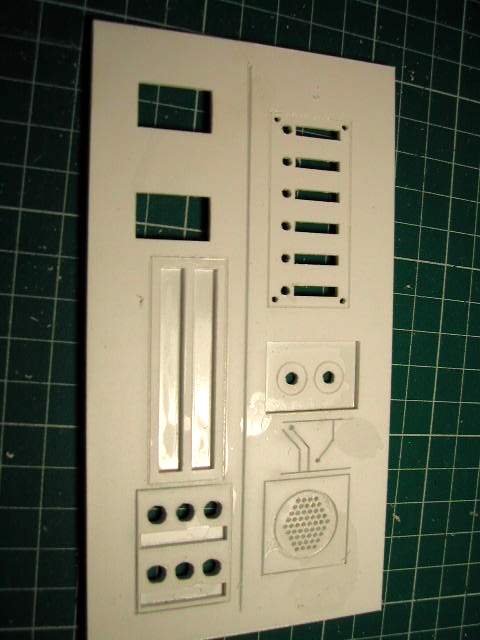
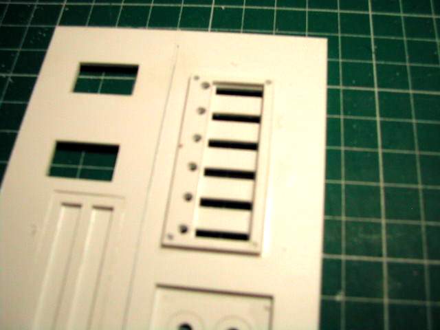
Here are the 2 panels glued togethter
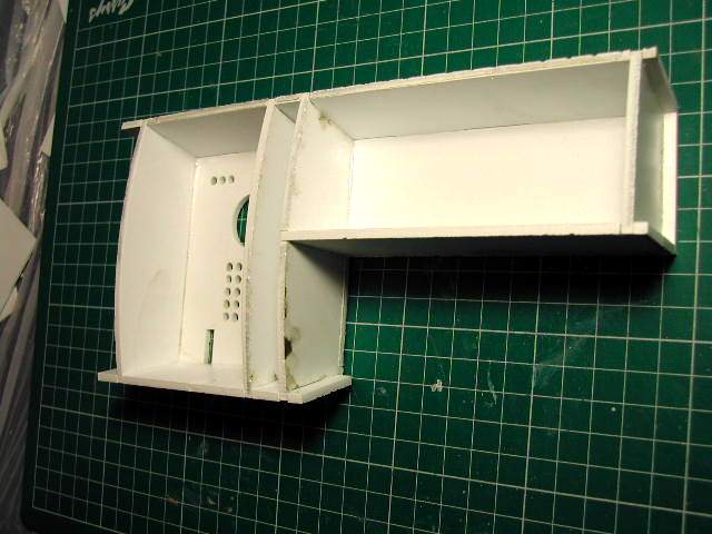
My prototype had this small frame that is not included in the kit and is not seen in the references. I decided to add it to give the panel some more levels.
Here it is installed
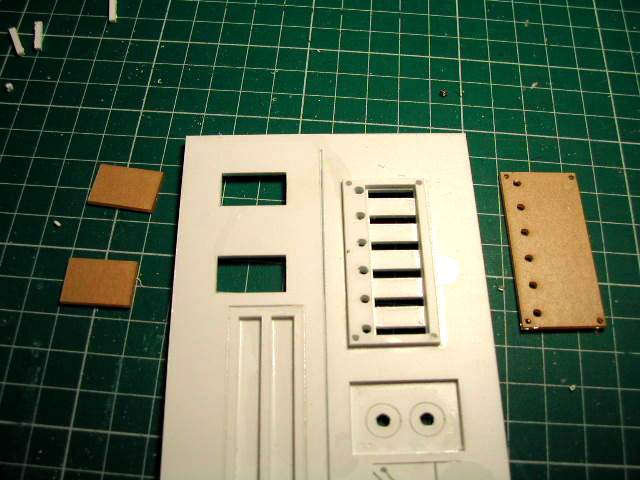
Now for the clear parts that still have their protective paper on them. At this point you should paint your panel as it will be much easier then after you put on the clear parts.
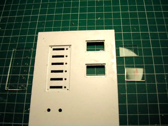
The above panel turned on it's back and the clear parts have had their protective paper removed.
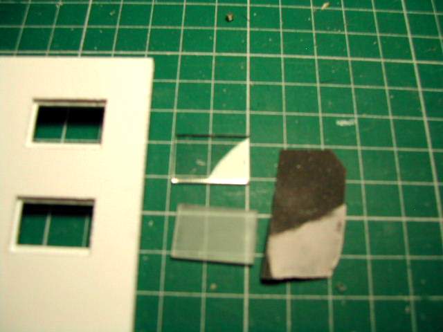
I took some 600 grit sandpaper to both sides of the clear parts to make them fogged. This will also help diffuse the lights I will put behind the panels later
The clear parts installed
The rear panel installed into the main panel and you are done.
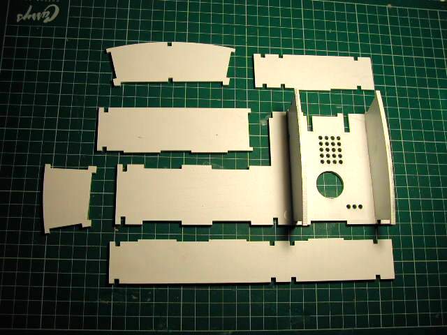
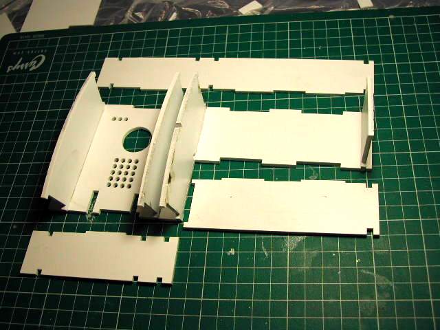
This is the layout of parts for the charging bay and the box below it. This kit was designed to fit easily into the A&A frame. With some modifications it will fit other frames also.
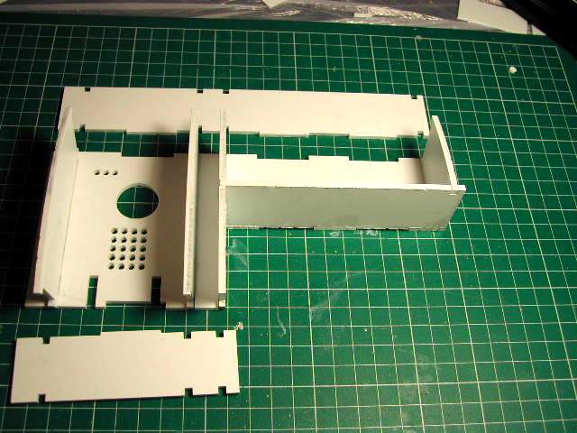
Right panel glued on
Second panel glued on
3rd panel glued on. Before you glue this part on check the photos below to make sure you have the part orientated correctly. Slight notches have to go a certain way so that a panel later on will fit
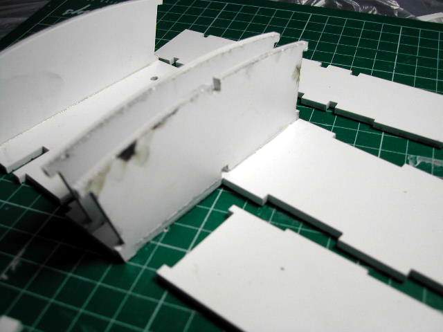
Here is the bottom view of the panel that has to go on a certain way
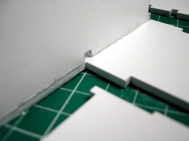
Close up of the panel and the notch that a panel will go into later on
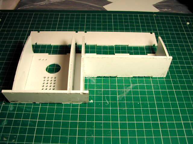
Now the 4th panel is glued on
This is the panel that you will have a problem with if panel no 3 is installed incorrectly.
The 6th part has been added
And the final part has been glued on
A finished view
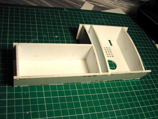
More views
and more
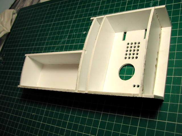
A close up of the charging bay