|
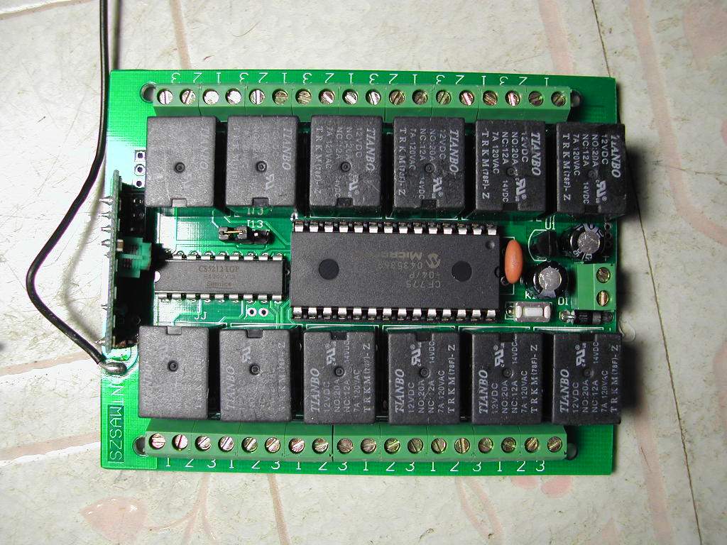
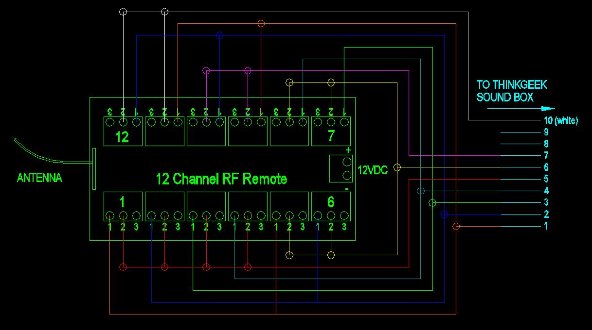
New Sound System This tutorial is based on the Thinkgeek Sound Tshirt What this setup (like the CFII, CFIII Cound Card and VMusic module) Items needed There are a variety of remote control systems that can be used but Once you get familiar with the buttons and sounds you should be Tools Needed The Tshirt comes with a variety of sounds written on a Here is the layout of the numbered wires and corresponding buttons Wire 1 + Wire 5 = Button 1 That's for all the sounds 1+ 10 = increase volume Pin #10 is the white wire We will be wiring the wires to all the NO (Nomrally open) relays. You want the 12channel rf remote to be on momentary as opposed In my case I am using only one remote with 10 sounds. The 11 and Check my other tutorials for using more then one remote if you want Note that wires 8 and 9 are not used. Pros Cons If you are not happy with the sound level of the supplied speaker you can replace
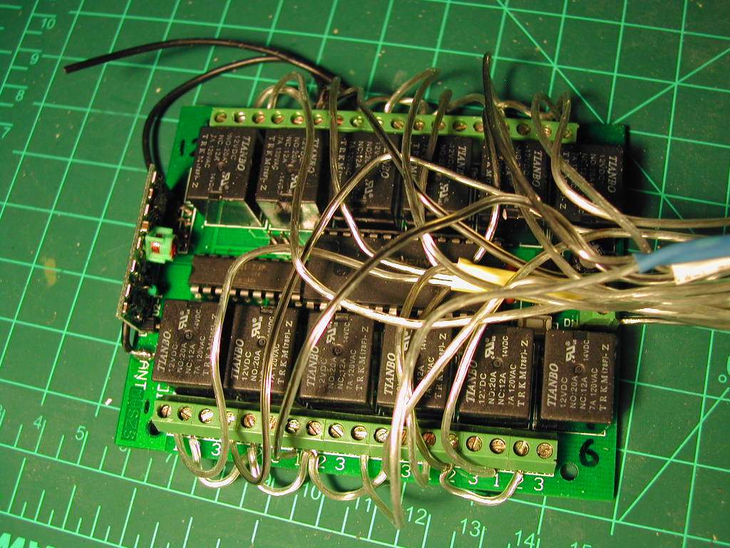
I recommend you power up the board and check the remote to make sure you have the power If you have a multimeter you could check to see which relay is the normally open contact |
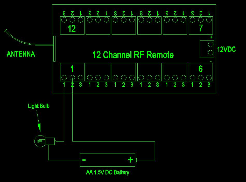 6512.jpg Here is a wiring diagram of a circuit to check the relays. Here I have used a AA battery, some wire and a 1.5V incandescent bulb. If you apply 12V power to the boards and then press the No 1 button on the remote the receiver should click and the light bulb should go on. |
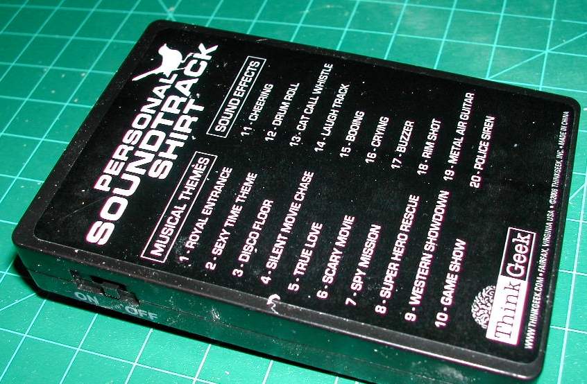 6502.jpg Here is the main body of the Thinkgeek sound board. The numbers correspond to the supplied sounds on the SD card that we will replace. |
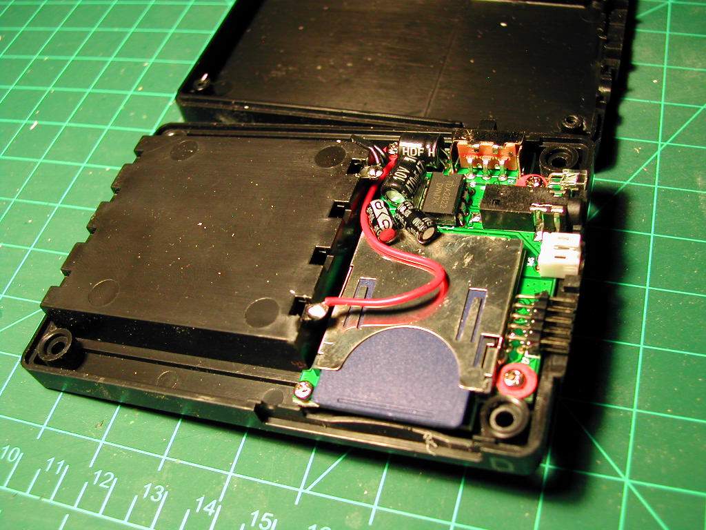
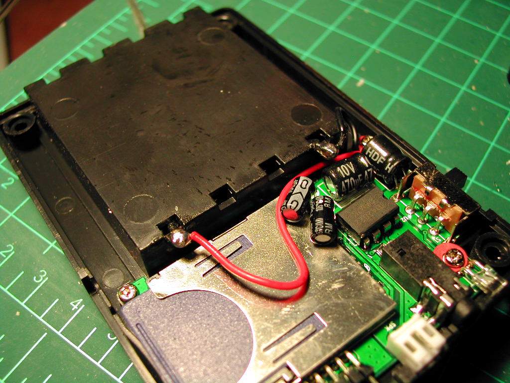
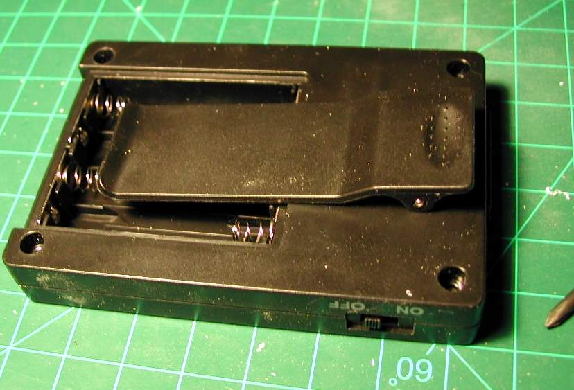 6503.jpg This is the back of the sound box with the battery cover removed and the locations of the 4 screws that need to be removed to gain access to the inside of the board for the wiring we will add. This wiring will allow me to use an external 6VDC power supply instead of relying on batteries. I will use an auto car adaptor to change the main 12VDC power supply in my droid to hte 6VDC power needed for the ThinkGeek Shirt |
 6504.jpg Before working on the sound box I have removed the speaker and the keypad wires These are connectors that are just pulled out. They are handed so they will only install one way. This makes working on the box much easier. |
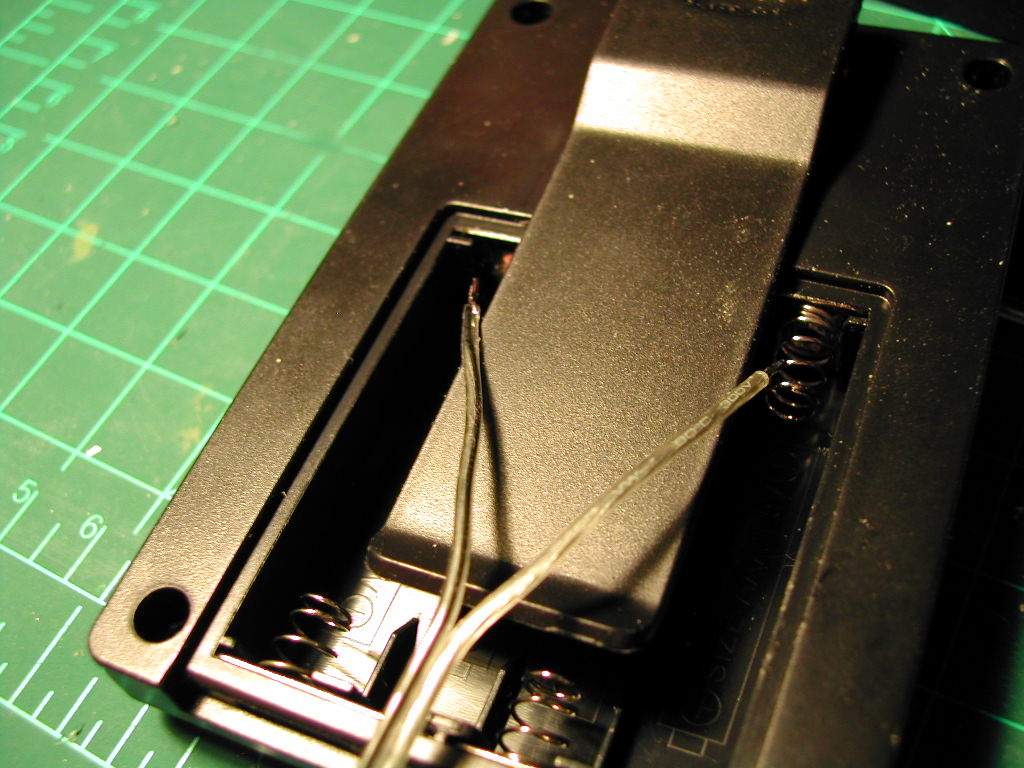
 6505.jpg Here is the inside of the sound box. The arrows show where there are 2 holes leading into the battery box which we will use. |
 6506.jpg Here is a wire I will be adding to the control box. They are split so they will be threaded into the existing holes for soldering. Make note of which wire is soldered to the black wire as this is the ground connector. |
 6507.jpg Here are the wires sticking into the inside of the control box |
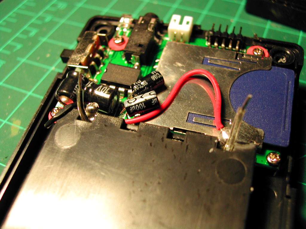
 6508.jpg Not easy to see but the wires are now soldered to the exisitng leads |
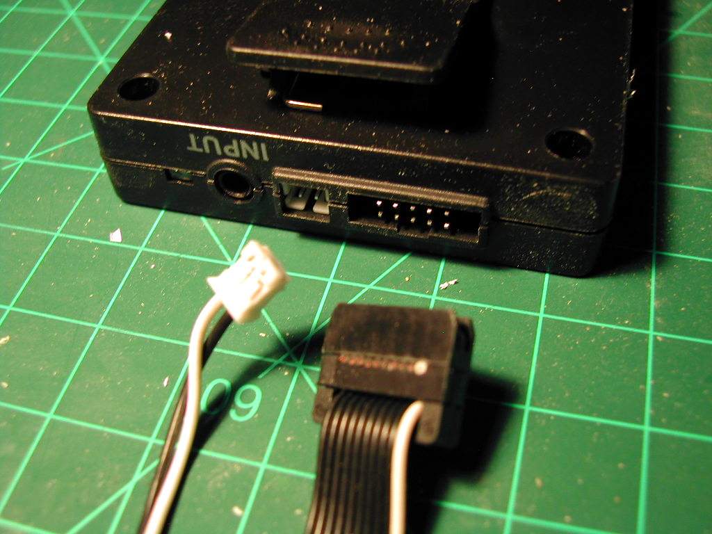
 6509.jpg Now the messy part. You have to cut off the keypad and add wires to the end of the ribbon to hook up the remote receiver. The wires are all soldered and then protected with heat shrink tubing. Electrical tape will work here too. |
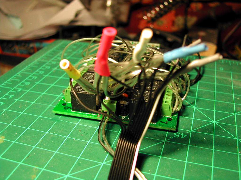
 6510.jpg It looks like a complete mess but if you follow the wiirng diagram bellow hopefuly things will make sense. |
 6511.jpg You can use a Dan S power distribution board or in my case I used an cheap automotive DC-DC converter. I cut off the 12V automotive plug and wired the power into my circuit. |