Nov 26 2007 - Last updated Nov 30 2007
This joint project was undertaken by Murray Jones and myself to develop a new sound
system very similar to the CF2 and CF3 system but cheaper.
Goal:
A system that the droid wrangler just pushes a button on a remote to get an
R2 sound. (or any other specific sound) The sounds are grouped according to
types (ie sad, enthusiastic, chatter, etc). This way the droid wrangler has
to worry about only 3-4 buttons and still get a variety of sounds. The type
of sounds and the grouping of sounds is entirely up to the individual
THE PARTS - (Prices on Nov 23 2007)
NEW SYSTEM
1. Vmusic2 - $45US
http://www.dontronics-shop.com/FTDI-VMUSIC2-p-16663.html
or
http://www.vinculum.com/
2. Picaxe 18 Project Board CHI030 $10US
3. Picaxe 18X IC $8.50US
http://www.rev-ed.co.uk/picaxe/
4. 12Ch RF Remote -$25
www.ebay.com
5. Amplifier kit $15-20
Http://store.qkits.com/moreinfo.cfm/QK88
Http://store.qkits.com/moreinfo.cfm/FK608
TOTAL: $110US
OLD SYSTEM
1. CF3 with Contact Sense 24 $241US
Http://www.acscontrol.com/Merchant2/merchant.mv?Screen=PROD&Store_Code=ACS&Product_Code=ACS-CF-CFSoundIII&Category_Code=AUDIO
2. 12Ch RF Remote -$25
www.ebay.com
TOTAL: $256US
So with the new system there is a potential savings of $146US. shipping
costs will decrease that number. Of course the CF3 system comes with a 25W
amplified while the amplifier kit shown is only 15W per channel. Not included
are the prices of the CF card or USB Drive.
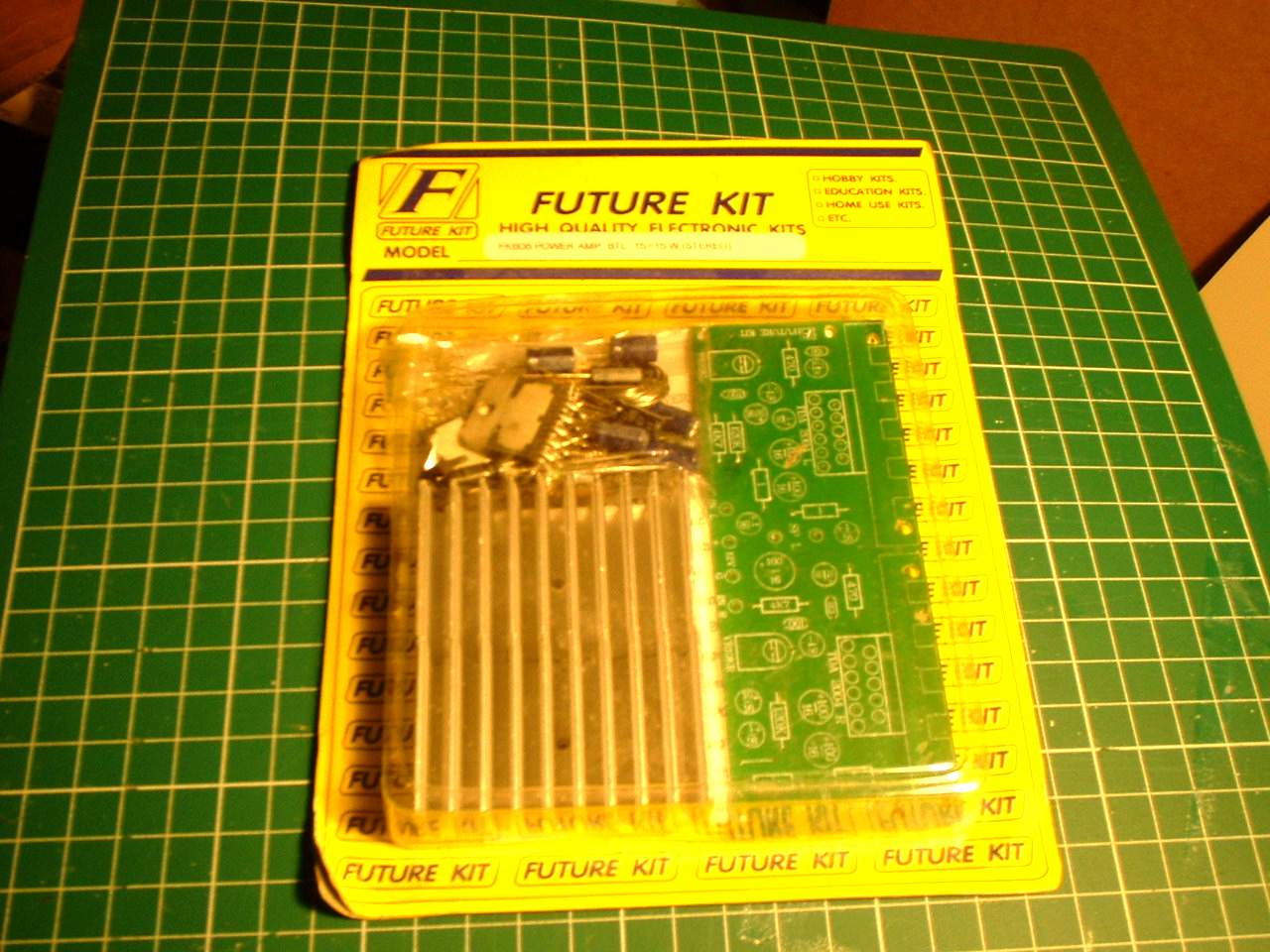
An example of a 15W per channel amplifier kit that will have to be soldered together. Not needed if amplified speakers are used.
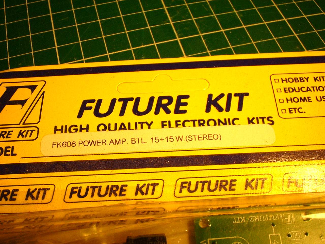
Close up of the kit
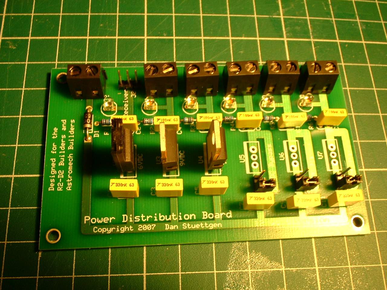
This is Dan S' Older Power Distribution board. Not needed but in this setup you need a 5V and a 12V power supply. Dan's board outputs 6V and I have had no problems with it so far
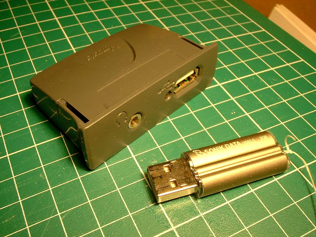
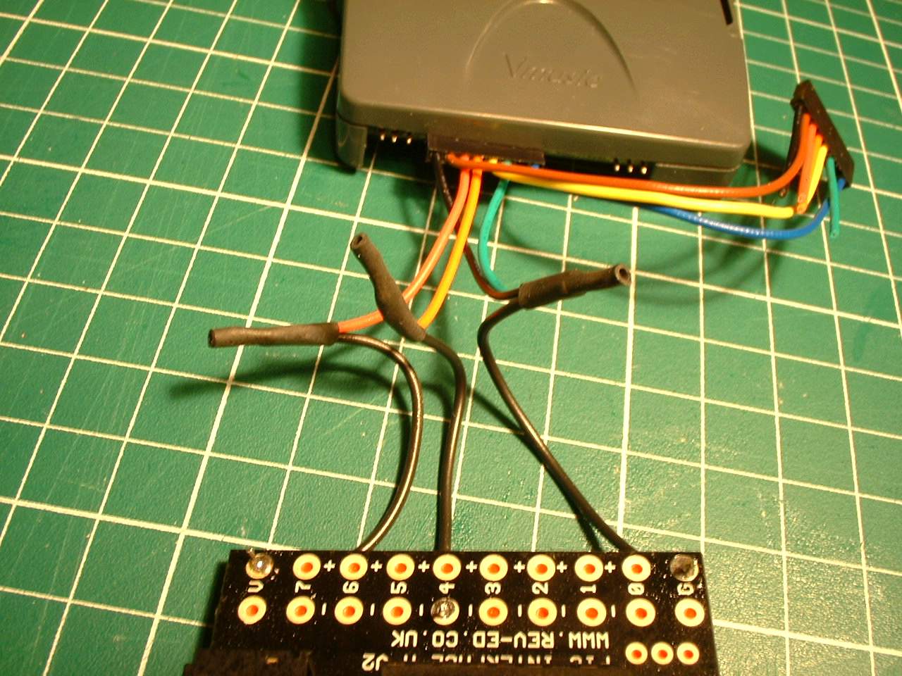
The Vmusic2 module and a USB 2.0 Drive. I had problems with a USB 1.1 Drive
The 12ch RF remote with the momentary/latch jumper
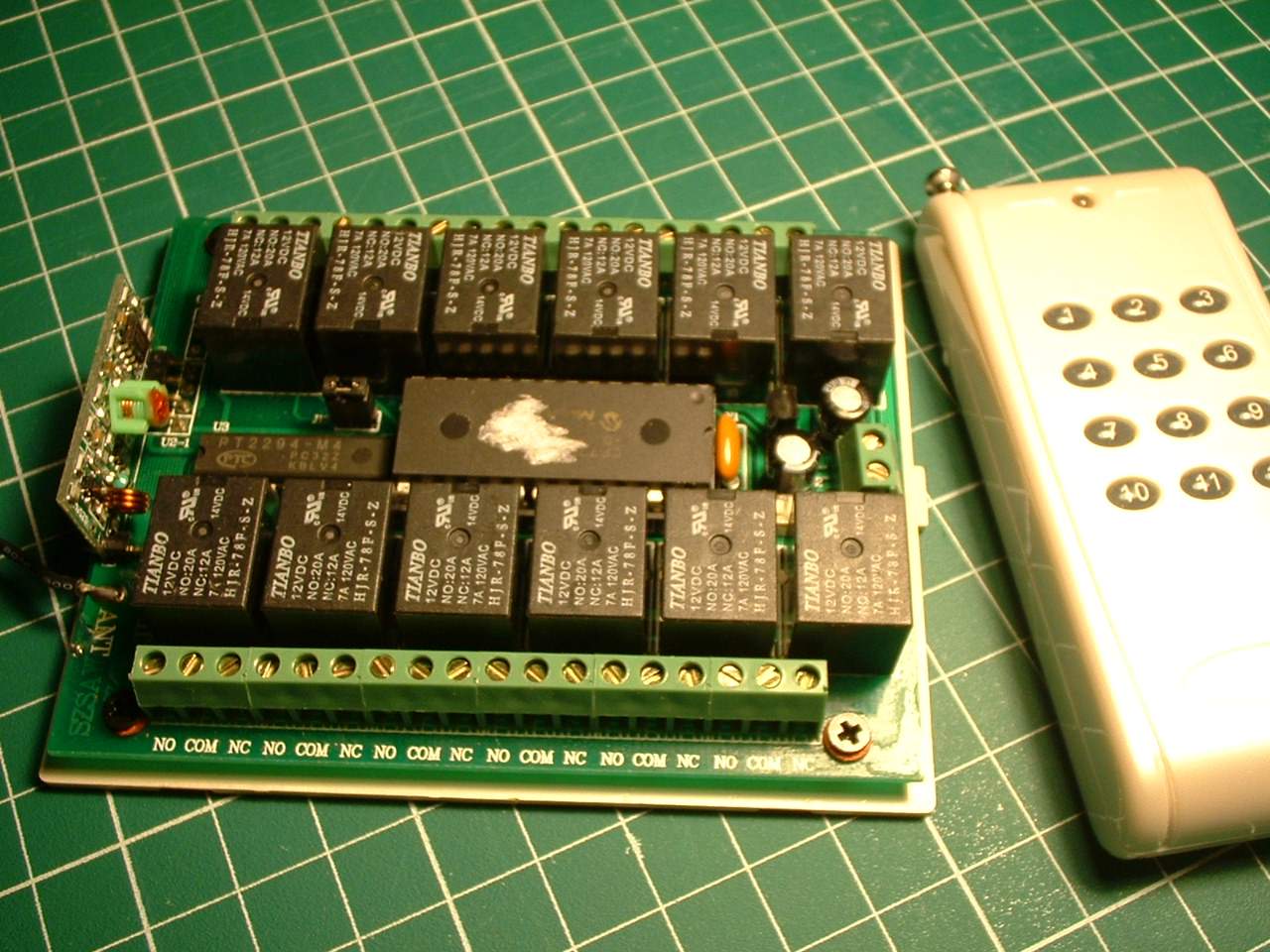
The remote with the transmitter
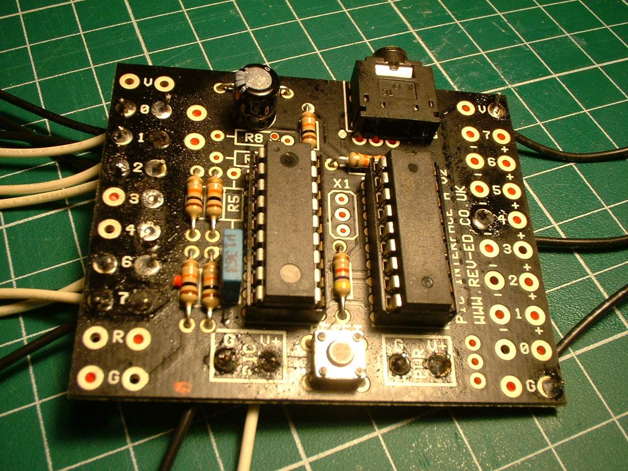
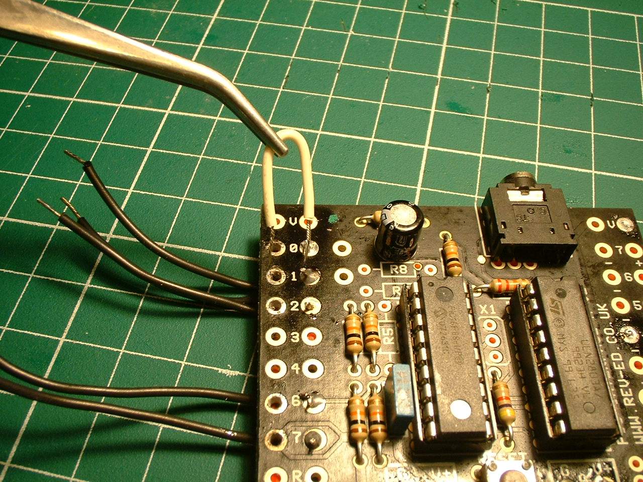
The PICAXE board with the 18X chip. Note the terminals used. The voltage terminals on the bottom are joined together (underneath) since there is only one voltage used here.
NOTE: You will need to add two 10k resistors to the circuit board to get it to work properly. If you do not you will go insane trying to figure out what is wrong like I did. ADD a 10k resister to positions R7 and R8
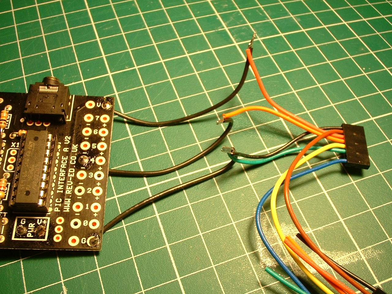
The connecting of the PICAXE board to the Vmusic2 connector. Orange, red, green and black are used. it is recommended that you wire up the PICAXE and Vmusic module first.
Then test these modules by applying power to the circuit and using a jumper wire to close the contacts 0,1,2,6,7 on the left. Plug in headphones into the VMusic module. If everytihng has been done correctly you will get sound. By working on the system step by step you can more easily trouble shoot if there are problems. In this case since the 12ch rf remote board has not been wired up and if there are problems we know it is not that board
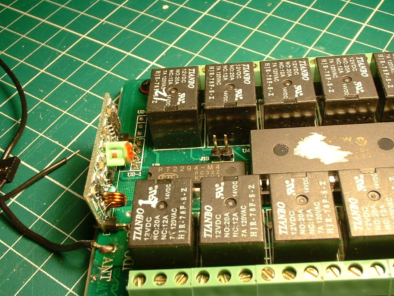
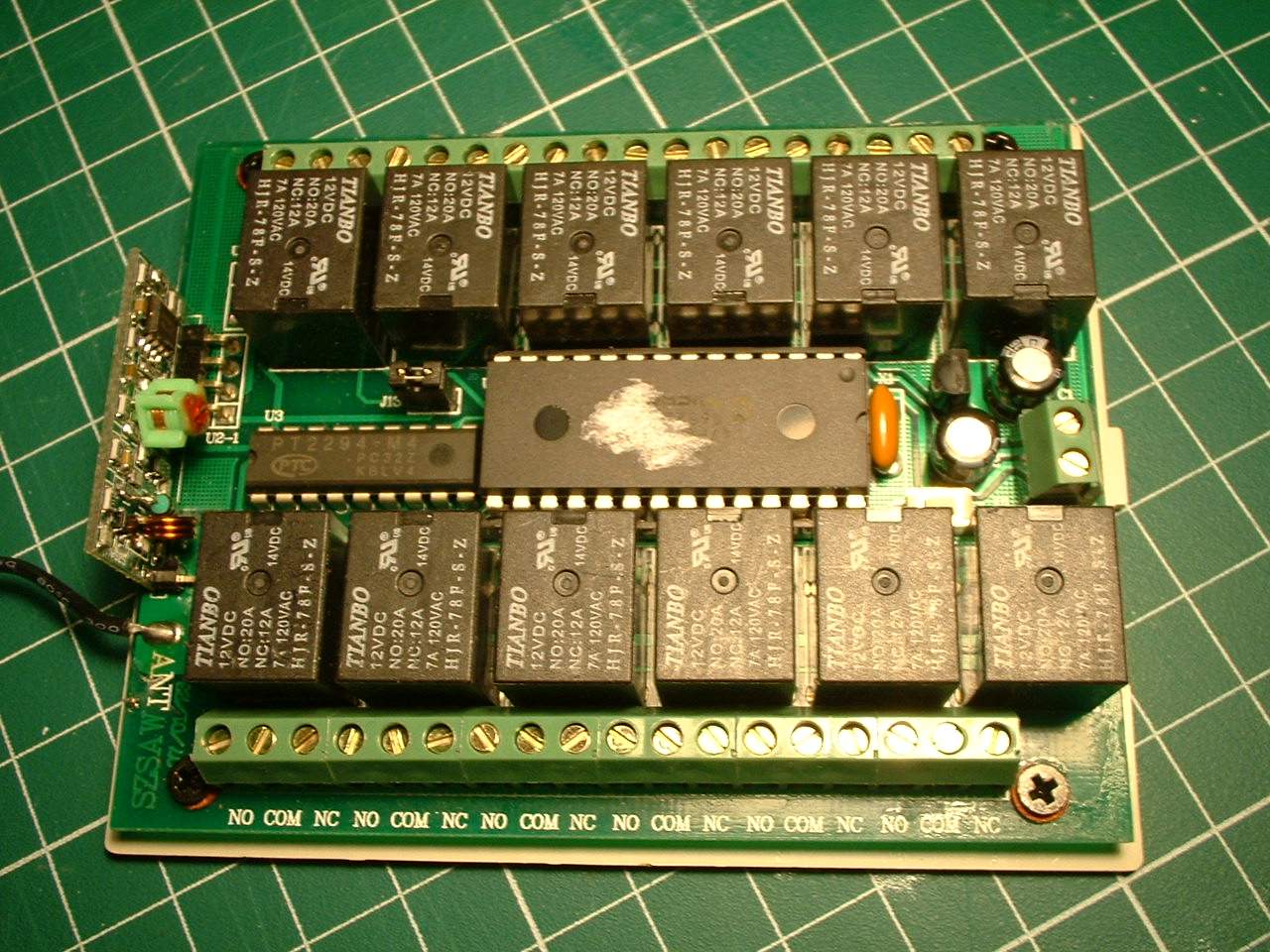
Close up of the 12CH rf remote with the jumper removed to make the board relays momentary when activated
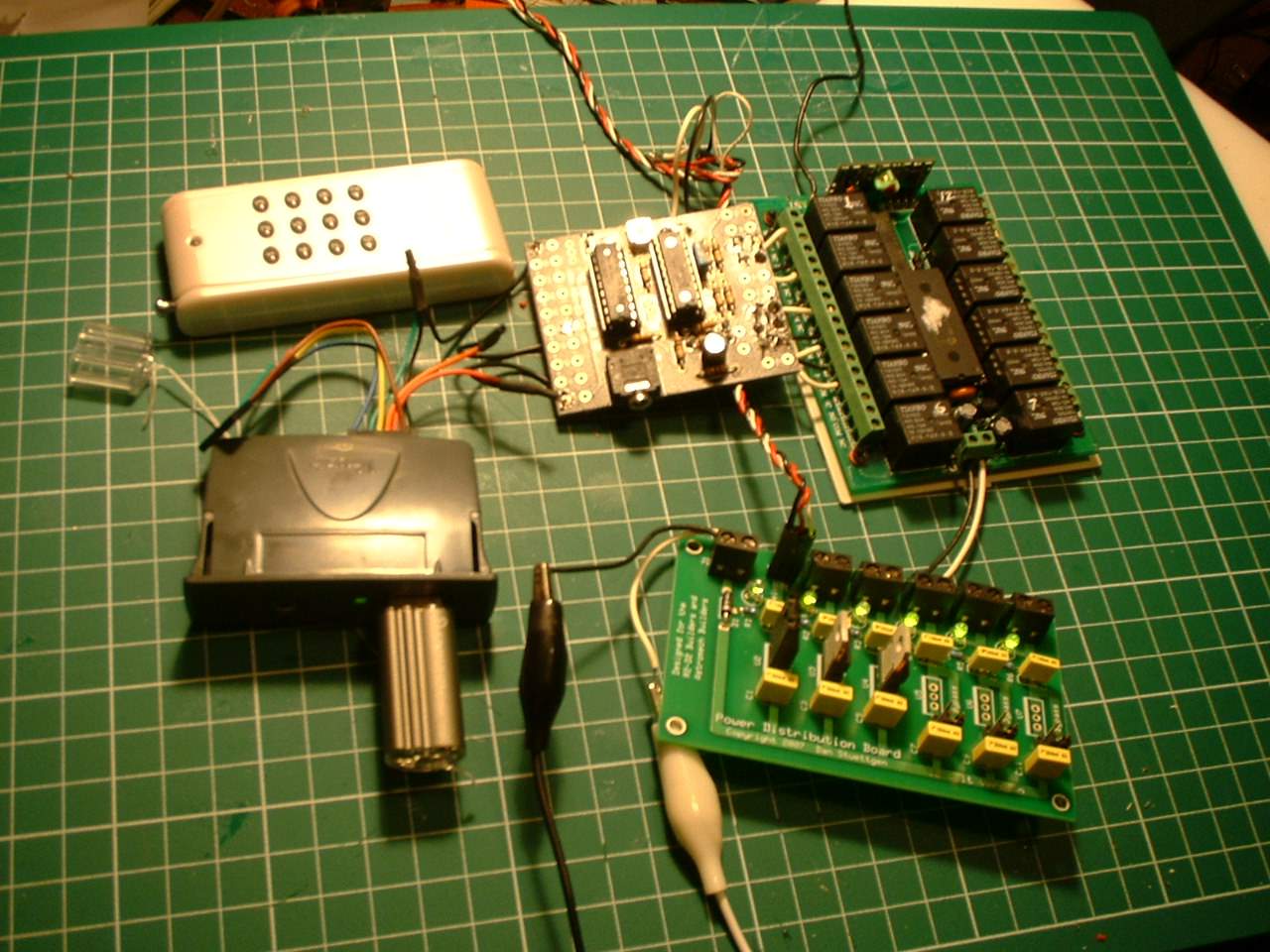
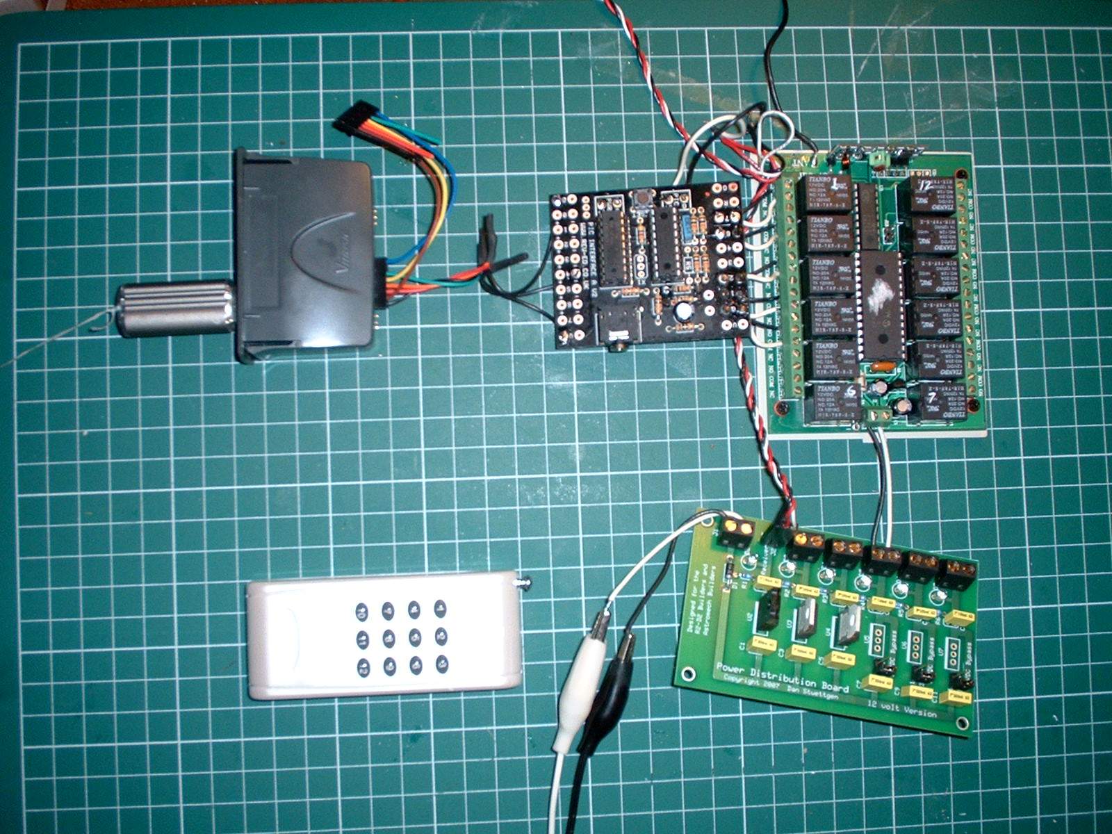
This is the setup all wired up and ready to go. The 2 alligator clips connect everything to one 12V power source.
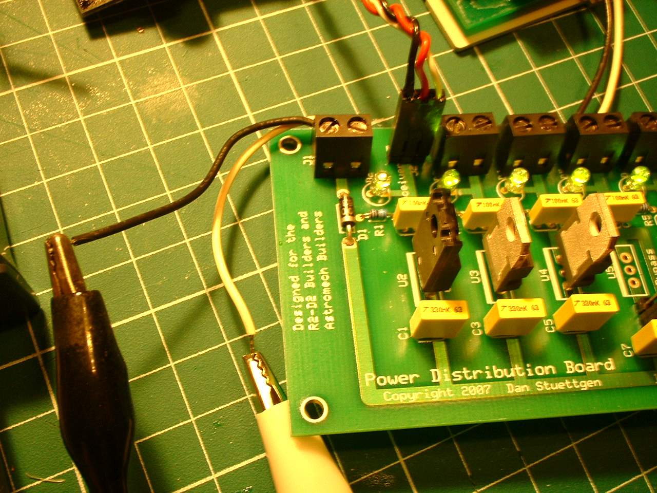
Close up of Dan's board. The connector for the 6V is a standard radio receiver plug that I have spliced into to power the PICAXE and Vmusic2 units. Dan's newer boards have 2 separate 5V supplies so this step would not be needed. For this phase of the project I just plugged in headphones into the Vmuisc module. Once I am happy everything is working I will add the amplifier circuit. If things do not work properly I do not have to worry that it maybe the amplifier board not working properly.
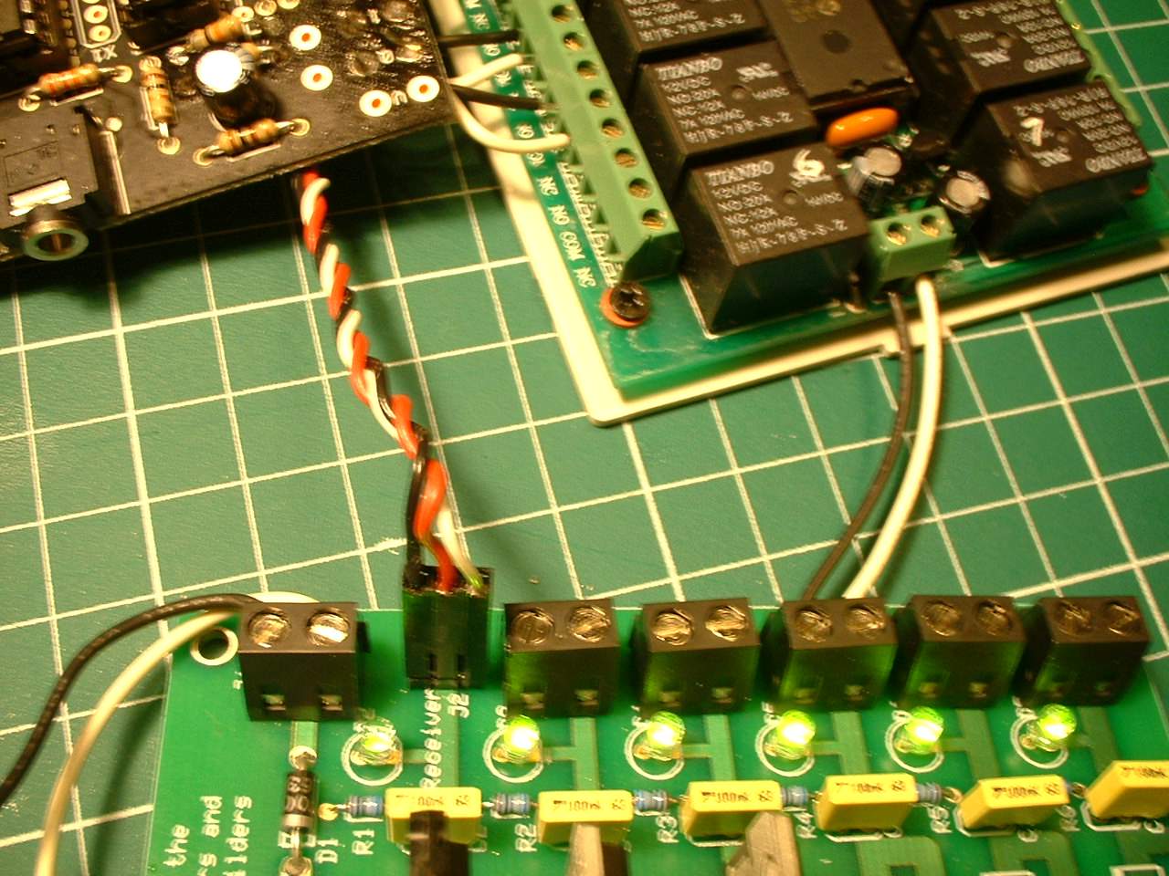
Left to right wiring explanation. 12V input source, Power to PICAXE and Vmusic modules, Power to the 12CH RF remote
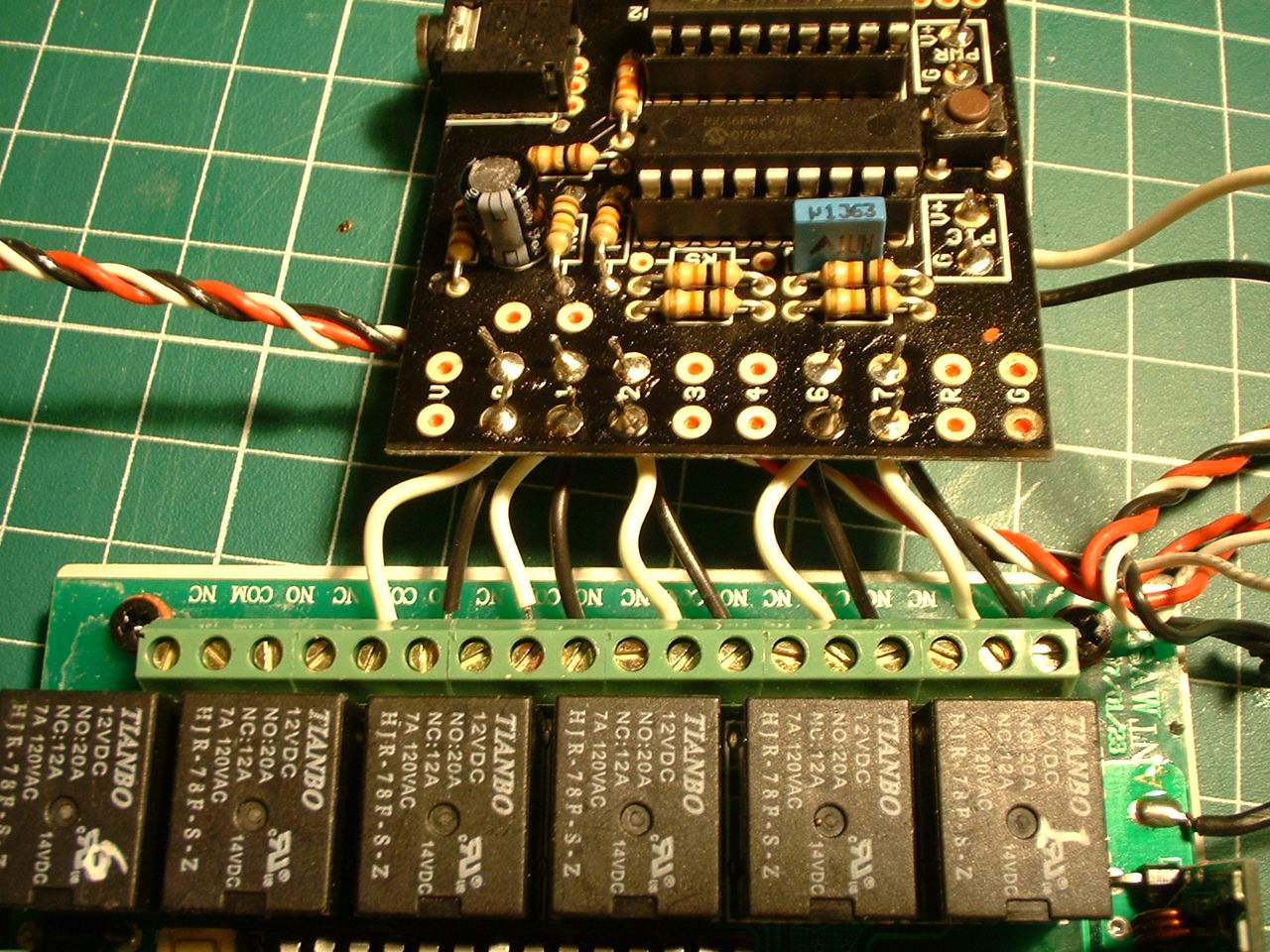
Close up of the PICAXE wiring to the 12CH RF remote (bottom) The common (COM) and the Normally Open (NO) terminals are used. In this setup we are using buttons 1 to 5. IF the builder is inclined they can change the button assignments as needed. Here we have left the other buttons (6-12) for future items. Someone might want the lower buttons (8-12) to control the sounds and the upper buttons to control stuff such as the HP lights or periscope up/down
Another view of the PICAXE to Vmusic2 wiring
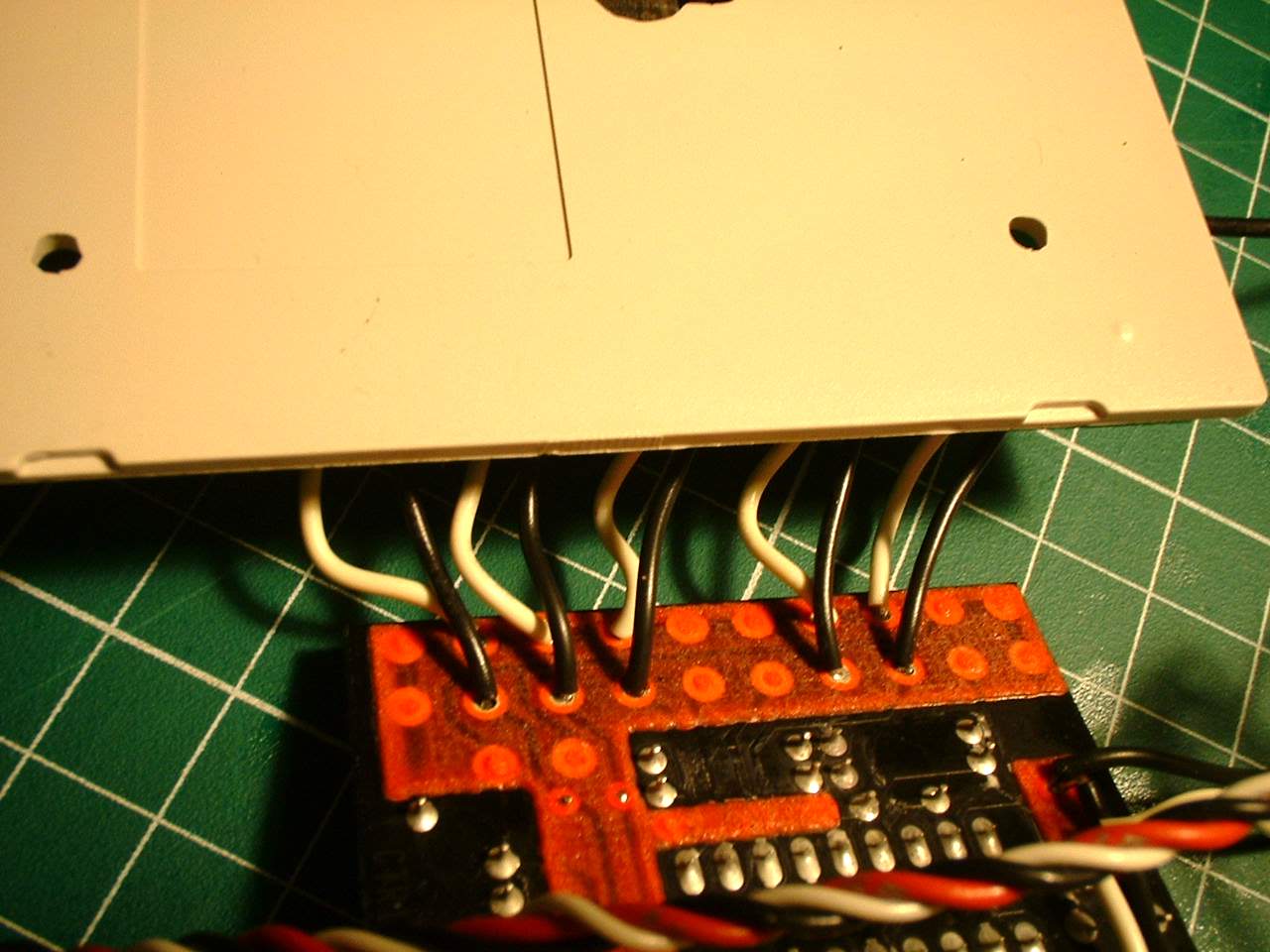
The underside of the PICAXE to 12CH RF remote wiring. On the right side you can barely see the wires connecting the power supply with the output supply. This option is avaliable so that if your output needed 12V it can be powered separately. The fact that both the PICAXE and VMusic modules need 5V means they can be powered from the same power supply.
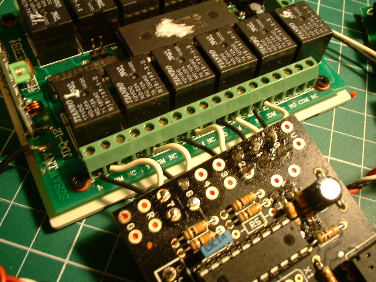
Another view of the PICAXE to 12CH RF remote wiring just in case the other photos were not clear
Overall Shot again. The amplifier board has not been added yet
NOTE2: Did you remember to add the 10k resistors to R7 and R8 on the PICAXE Board?
This system is slightly more work then the CF3 especially if you have to assemble the amplifier. However with the PICAXE it can be more flexible. I have it set up one specific way but it can be modified/customized by the builder if desired.
This is the way I have it set up on the 12ch rf remote and reflected in the files that can be downloaded
Mode 1
Button 1 - Generic R2 Sounds (9 different sounds)
Button 2 - R2 talking sounds (9 different sounds)
Button 3 - R2 sad sounds (3 different sounds)
Button 4 - R2 Special sounds (6 different) (ie scream, help me Obi Wan, short circuit, raspberry etc)
As a bonus Button 5 toggles between a second set of sounds 01.mp3 plays once or twice to tell you which mode you are in
Mode 2
Button 1 - One long file of R2 sounds with a 10 second gap between sounds. I play this when I am to busy controlling R2s drive and dome to play specific sounds
Button 2 - Star Wars Music (7 Files)
Button 3 - Sound bites from the Star Wars movies (12 sound bites)
Button 4 - Non-Star Wars sound bites (30 sound bites)
If desired button 5 can be programmed for more sounds or other modes. We are also looking at a mode where you can control the volume.
The program below is available so people can program their own PICAXE board. There might be an option of us programming the board for those who do not have the download cable. (and why would you not have the download cable as the PICAXE board is a wonderful tool for robots)
We have tested the program on only the 18X chip and board. It will most likely work on other X chips but since the boards can be different it is unknown if they will work properly without slight modifications. It needs the X chip as the Vmusic module needs to communicate in 9600 baud which the regular chips can not handle
Downloads
PICAXE Program (Murray and Alex Vmusic Sound File Version 13) - program to be downloaded into the PICAXE 18X
Zip file of mp3 files that work with the above bas file 11 meg - mp3 files that are placed on the USB 2.0 drive (note the Star Wars music files are not included files 39.mp3 to 46.mp3) See below for a link to the entire file. The builder can include their own mp3 files just rename them 39.mp3 to 46.mp3
Link to Astromech Factory where the full 44 Meg file can be downloaded - no membership required
PICAXE Electronics for Astromechs by Murray Jones Ver 2.5 2 Meg - A basic introduction to the PICAXE and what it can do
For Questions on the PICAXE you can email Murray murrayj at supernerd.com.au or join the Astromech Factory Forums and ask questions there