This is the (preliminary) tutorial for the A&A Astromech Feet flat pack. The material is mainly 0.125 Styrene sheets laser cut. To ease assembly some edges that meet, are keyed to interlock. However this does mean puttying will be needed to get a nice finish. This problem could have been reduced with thinner material but then the foot shell would not be as strong. It is all trade offs due to the limitations of the laser cutting process. The ideal method would have no keyed edges, however the builder would have to bevel each edge for a tight fit. It is not impossible but the skill level needed to assemble the parts goes up several degrees an we wanted to make it as easy as possible for teh builder to achieve decent results.
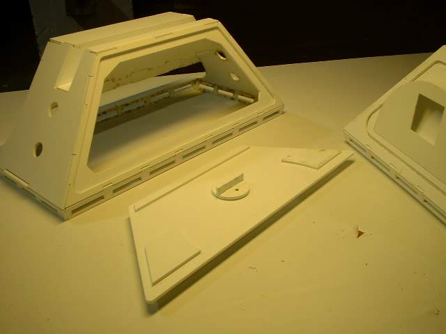
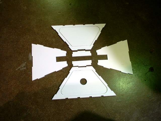
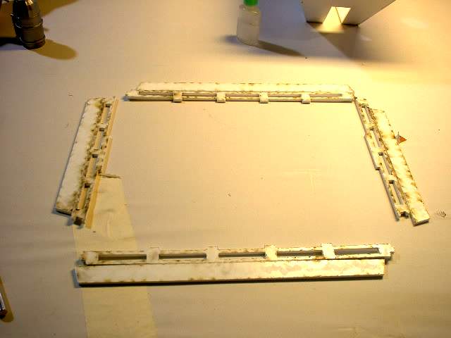
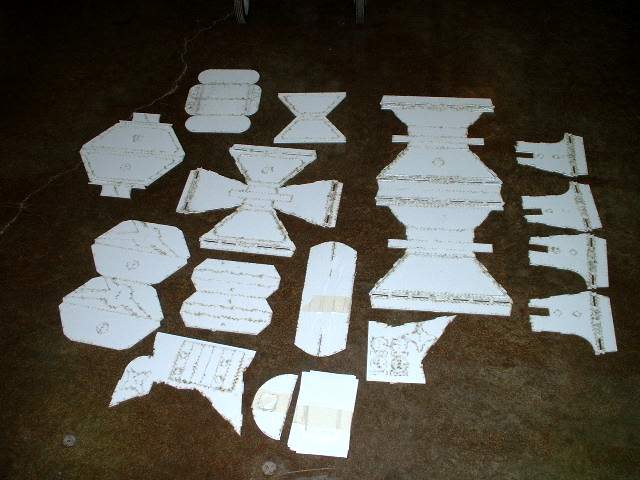 aafp01.jpg Layout of the parts (Note this is a prototype set so the middle foot door system is missing) |
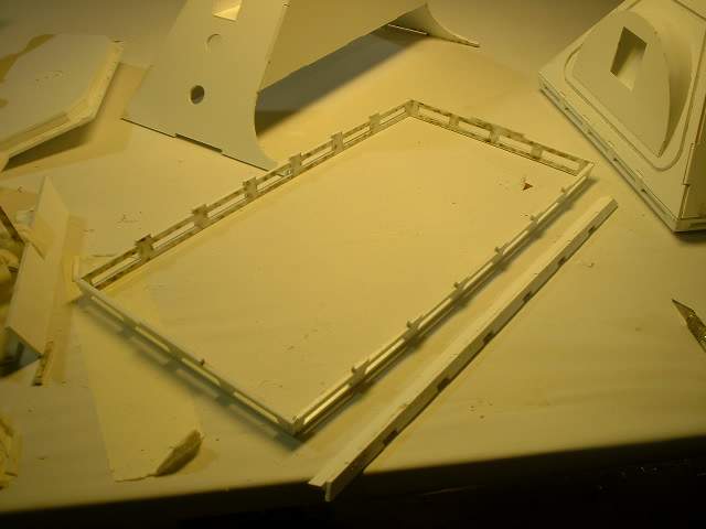
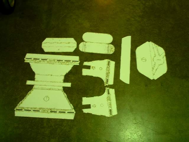 aafp21.jpg Here are the pieces for one side foot shell |
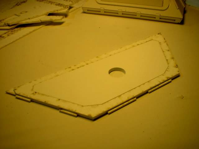
 aafp22.jpg To use the door system we first glue all teh 4 side pieces together. The bottom shows the front outer ring and the back piece. The rear shows the front piece on top of the inner piece (not seen) |
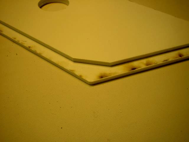
 aafp23.jpg Here is the back sire view. The bottom back piece comes right to the edge of the front piece. The top shows that the back piece is only slightly smaller then the front piece |
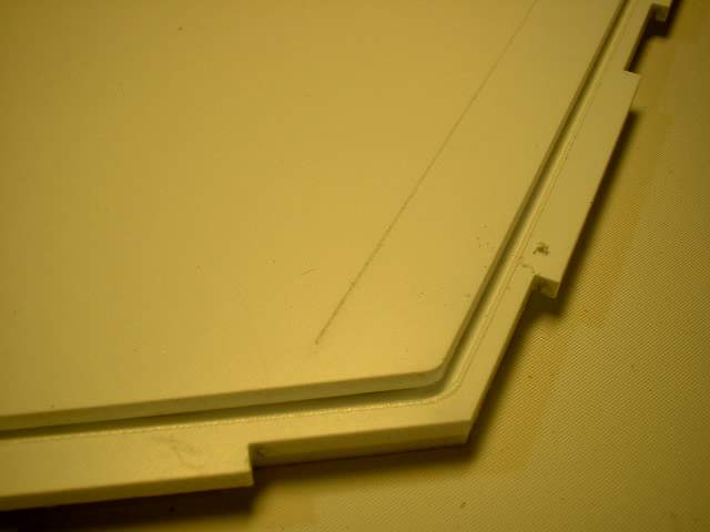
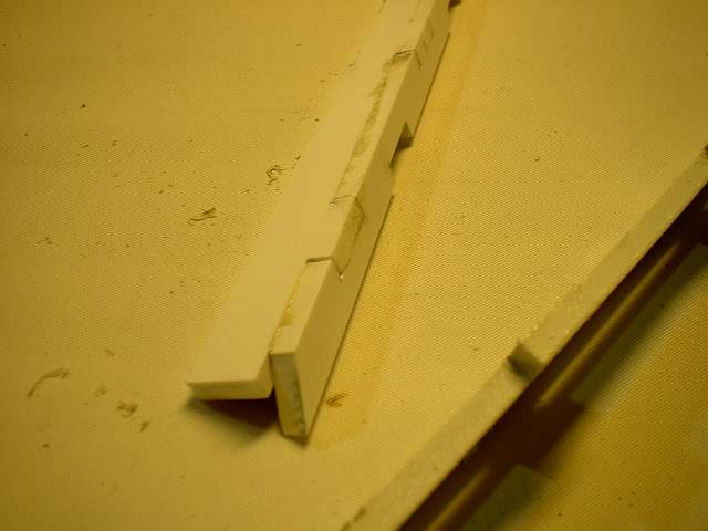
 aafp24.jpg Close up of the outer ring (bottom) and the backing piece (top) and showing how they line up |
 aafp25.jpg Another view showing how they literally line up |
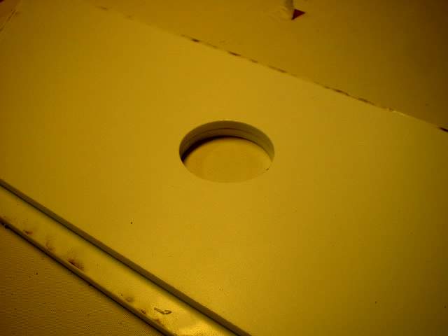 aafp26.jpg Here are the inner pieces (back view) with the outer piece on the bottom and the inner piece on top. The hole in the middle is used to line everything up. |
 aafp27.jpg The spacing all around has to be even or the assembled pieces will not line up |
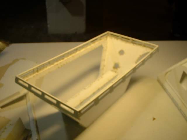
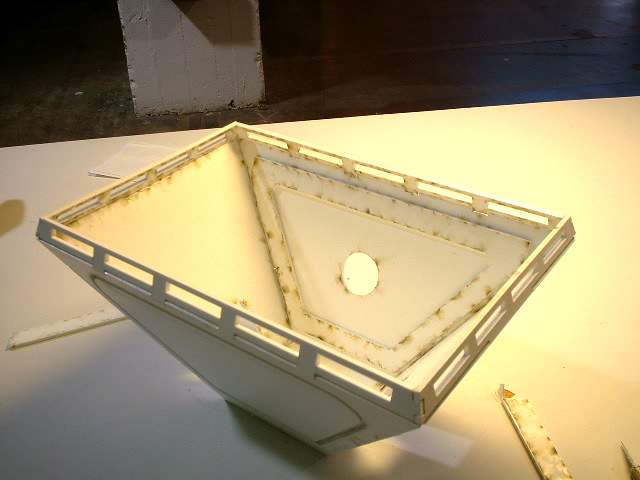
 aafp28.jpg The moment of truth. The outer rings are placed down first and then the inner piece is placed inside. here you will find out if everything fits right |
 aafp29.jpg Another view |
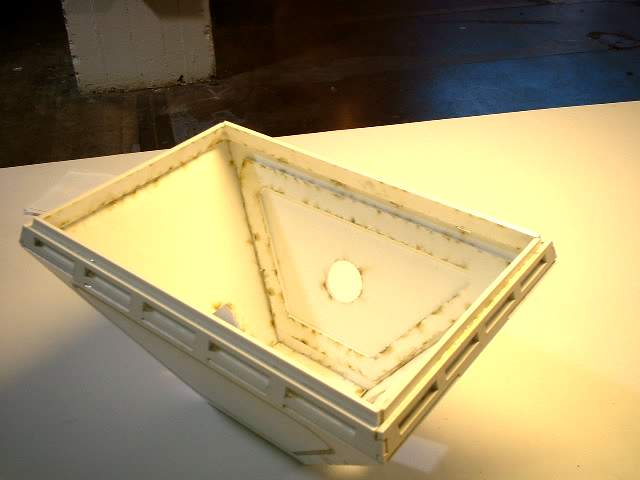
 aafp30.jpg Close up showing the recessed groove that is supposed to be even all the way around. If it is not hopefully the glue has not fully set and you can reposition the parts until they lineup |
 aafp31.jpg Another view |
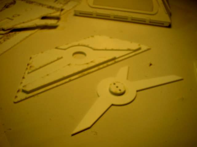
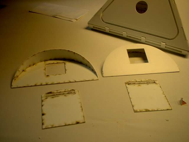
 aafp32.jpg Now for the door system if you want to use it to access the inner workings of your drive system without taking the foot shell off. Not the perfect solution but better then nothing. These are the parts you need |
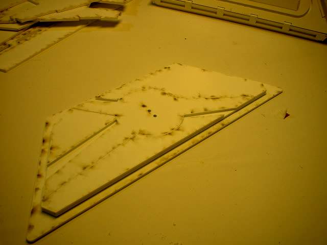
 aafp33.jpg The outer pieces have been glued to the back of the middle piece that was assembled before. The edges of the middle piece as well as the middle piece were used to make sure the parts lined up. The middle piece shown here has been flipped over and the disc glued on. There are 3 holes used to line the parts up |
 aafp34.jpg We flip the middle piece back over and drop it in the space provided. Be warned that these parts are to be able to move freely so make sure there is no extra glue that may glue all your parts together |
 aafp35.jpg If done correctly the rotation of the middle piece will slightly overhang the top piece |
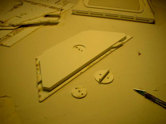 aafp36.jpg More fun as the moving parts are now closed off with a backingplate. Care must be taken with the glues as you do not want to get any on the movable part or it will not work. Every so often move the middle part to make sure it is still working. Also at the bottom is the handle parts glued together |
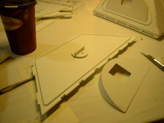 aafp37.jpg Here the handle is glued on. If there is a problem with the styrene disc being not tall enough to glue the handle on an extra disc made out of 0.020" is provided to slightly raise the disc so the handle can be glued on. Also seen below is the detail cover. For added strength find some rod the same diameter as the small holes and glue them in. |
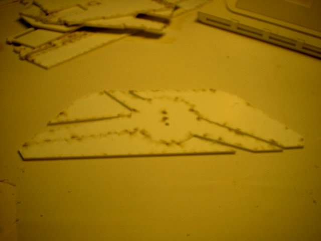
 aafp38.jpg Using the scribed lines on the foot shell the half moon is glued on |
 aafp39.jpg The other 3 detail pieces are glued on using the scribed lines as guides. |
 aafp40.jpg Next are the channel pieces and foot shell skirt pieces |
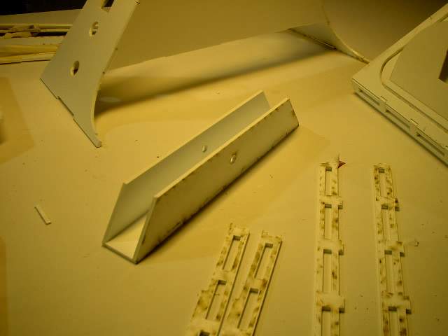 aafp41.jpg The channel is provided but does not have to be used as the drive system and ankle mounting point normally fills this area |
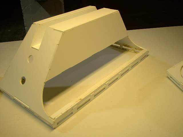
 aafp42.jpg The foot shell pieces are then glued together and the channel piece is ready to go in |
 aafp43.jpg Here is the channel glued in |
 aafp44.jpg I assembled the bottom skirt pieces to see if this method was better then trying to glue the parts on at a time to the foot shell |
 aafp45.jpg I the assembled the small side pieces that will be under the battery box |
 aafp46.jpg Close up |
 aafp47.jpg With the man foot shell turned upside down the slotted skirt is now glued on along with that small piece |
 aafp48.jpg And now flipped right side up |
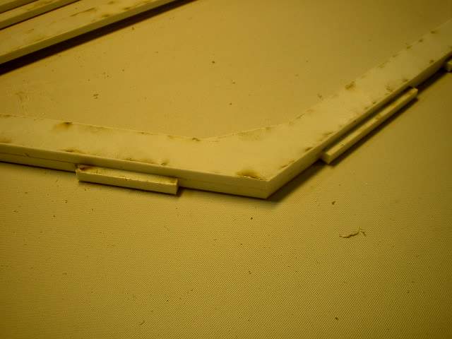
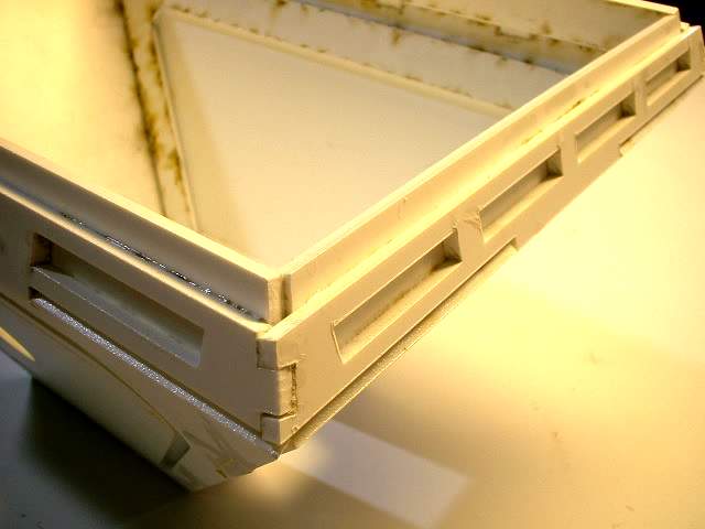
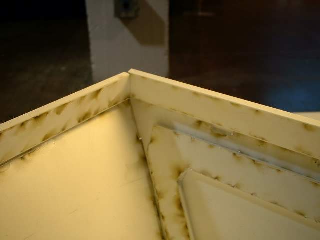
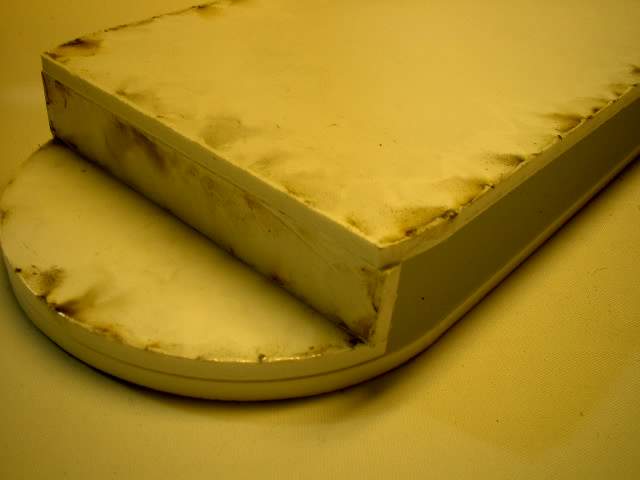
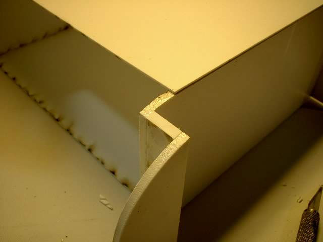
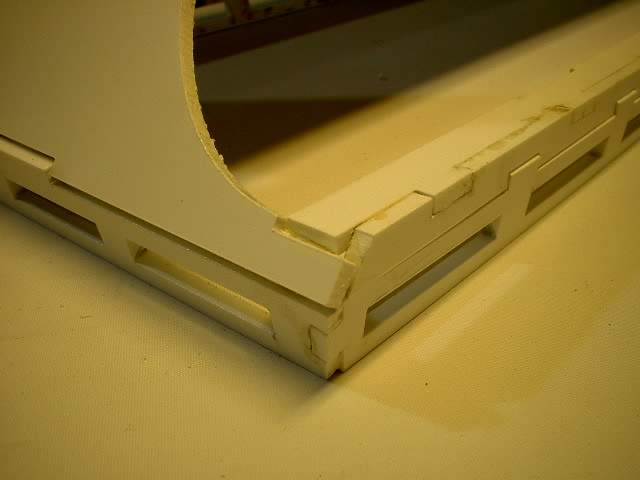 aafp49.jpg Close up of the corner and the inherant limitation of ths material and angled edges. |
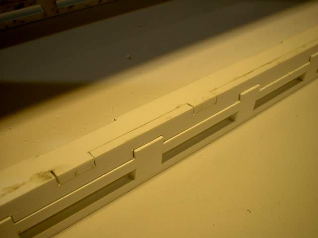 aafp50.jpg A coule of close up shots of the area under the battery box. |
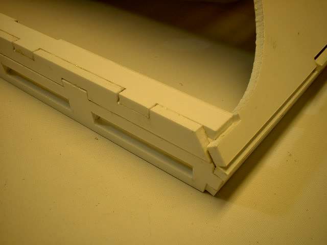 aafp51.jpg |
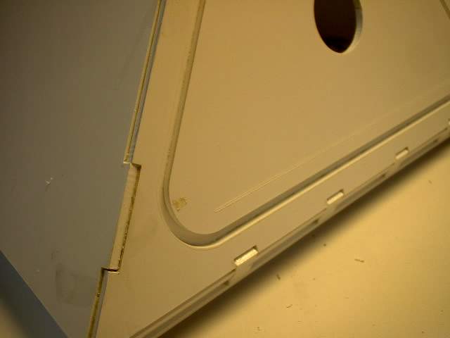
 aafp52.jpg Here is the side panel removed for access to the inner working so fthe drive system if needed |
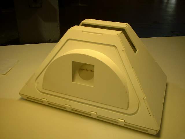
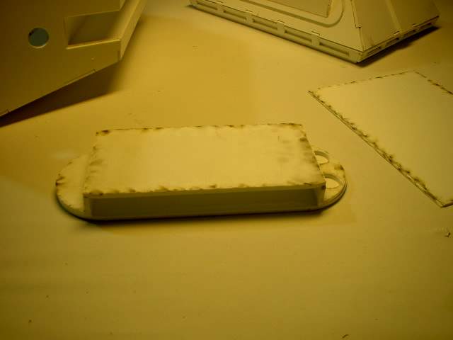
 aafp53.jpg And here is the door installed |
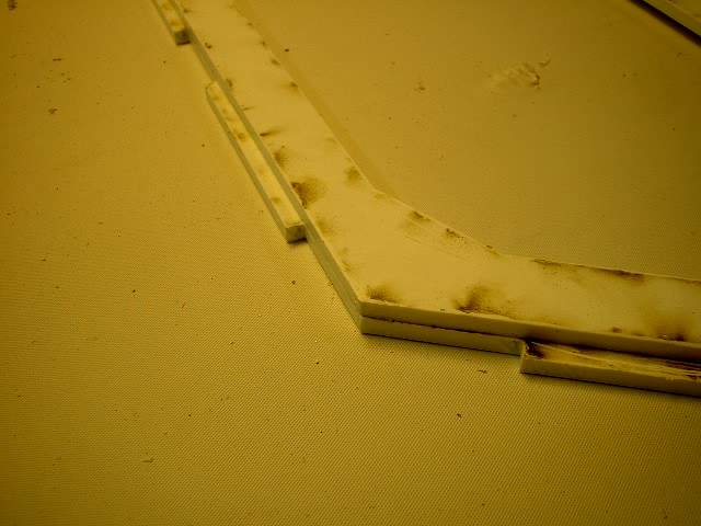
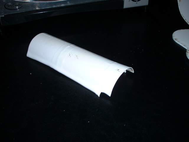
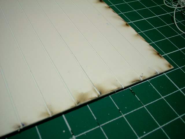
 aafp54.jpg Next is the curved section of the foot shell. It is not easy bedning styrene by hand so the materil provided here is much thinner then the rest of the kit. Even then it may not be easy to get a smooth curve |
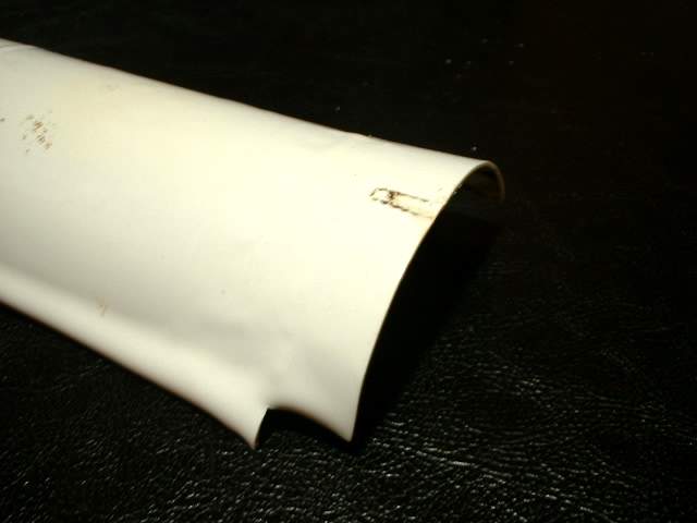
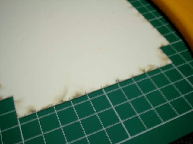
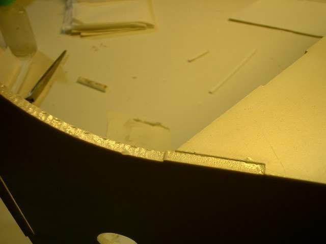 aafp55.jpg Again due to limitations of the laser cutting this edge needs to be cleaned up |
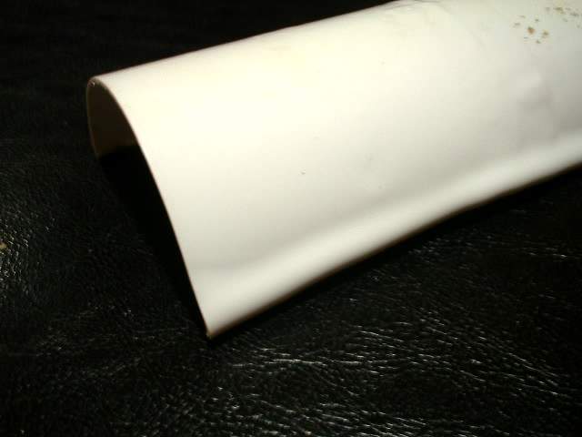
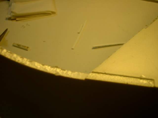 aafp56.jpg |
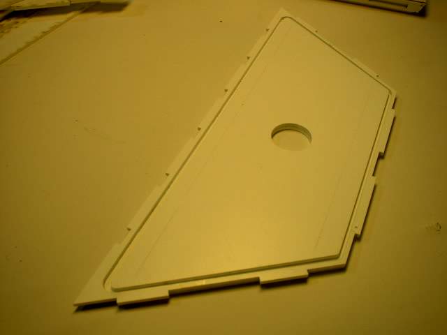
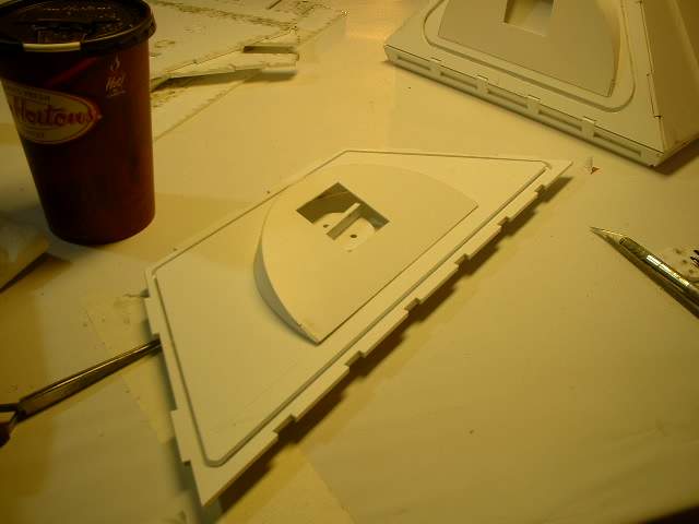
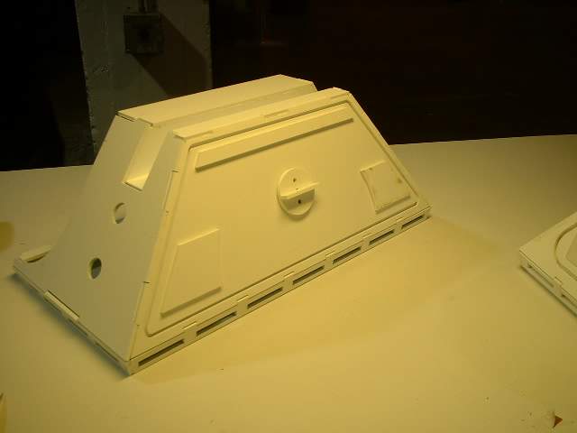
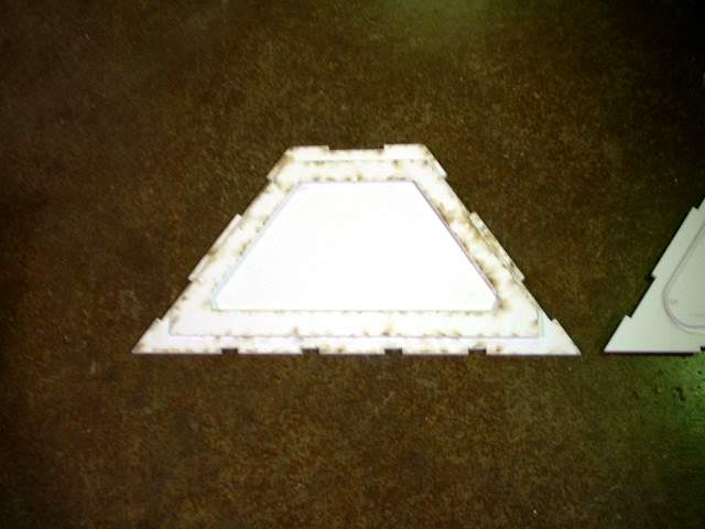
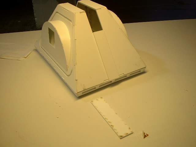
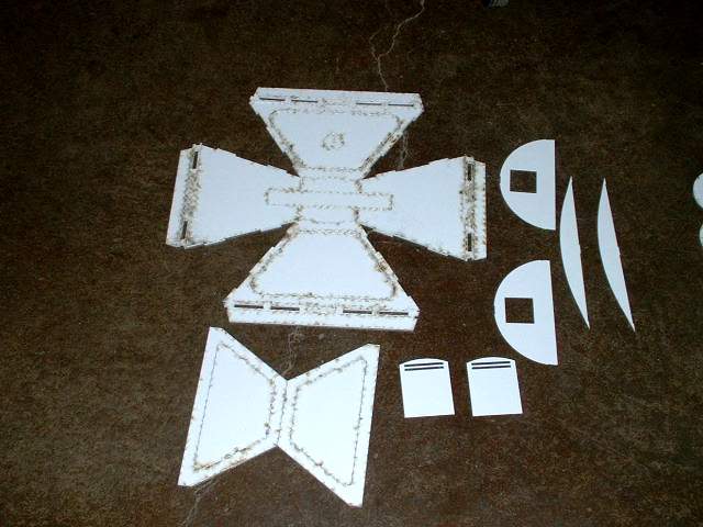 aafp02.jpg Let's start with the middle foot. Missing s hte door system but it is the same as the side feet. If you awnt to include that go to that section first and assemble the side feet to understand how it works and assembles before returning to the middle feet. If you do not plan to use the middle foot door follow this asembly procedure. These are the parts needed. Missing is hte middle channel and strips |
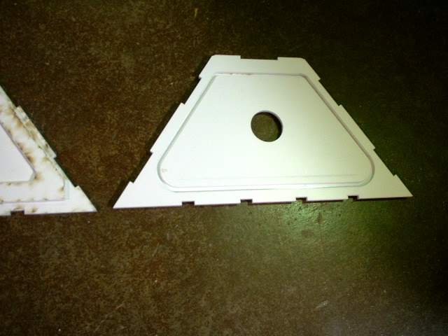
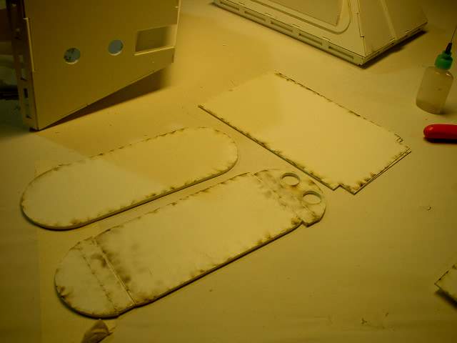
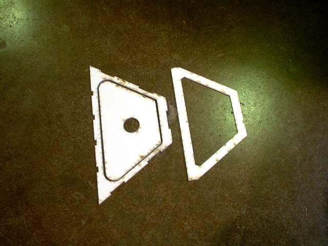 aafp03.jpg Take these pieces first. THe other side will not have the hole in the middle. Line them up and glue them together |
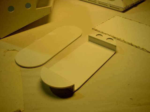
 aafp04.jpg Right - back side, left - front |
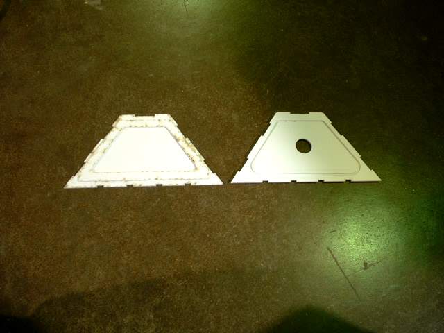
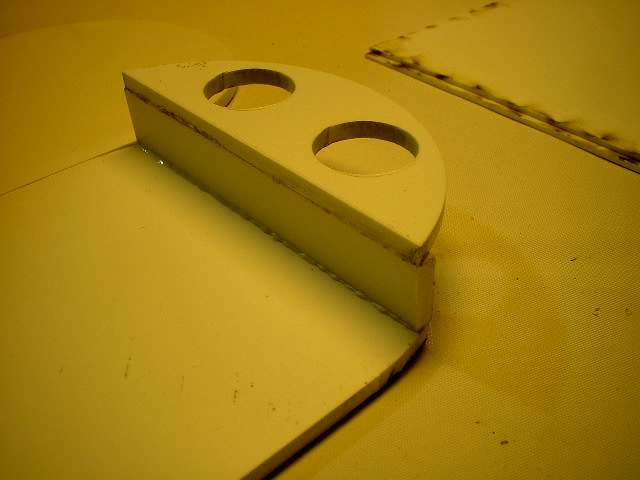
 aafp05.jpg Close up of the back showing the back piece lined up. This is needed for later when you asemble teh 4 sides |
 aafp06.jpg Close up of the back showing the back piece lined up |
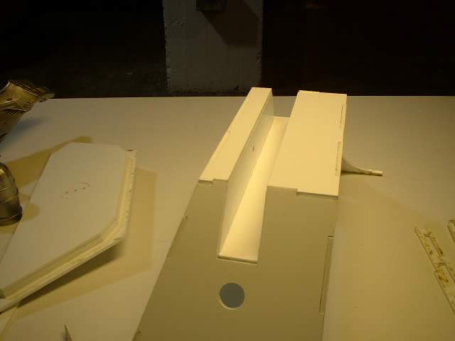
 aafp07.jpg Here are the pieces for the middle foot shell top. Note the inner channel is not shown as it was added to the kit later. See the side foot shell channel to get an idea of how it is assembled |
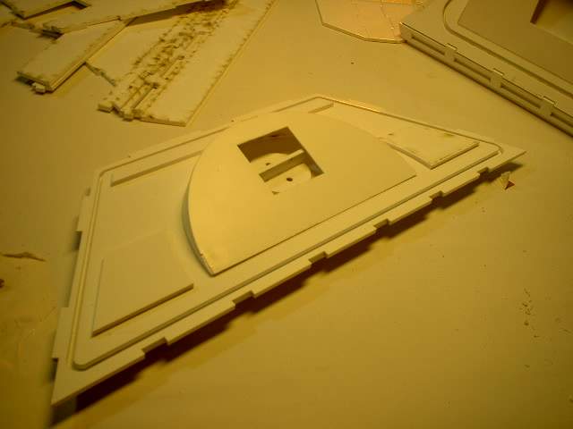
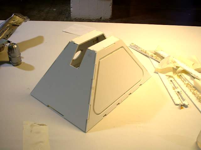 aafp08.jpg All 4 sides and top pieces glued together |
 aafp09.jpg Bottom pieces laid out |
 aafp10.jpg The first row is glued in |
 aafp11.jpg The inner skirt is glued in |
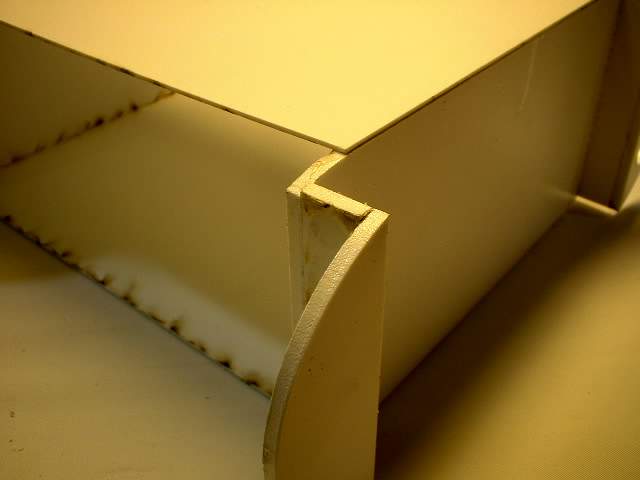
 aafp12.jpg Close up of the corner |
 aafp13.jpg Close up of the inside. The inner corners where the pieces meet should be reinforced. I plan to hot glue them ot add strength |
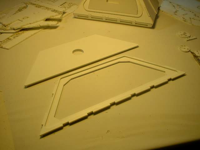
 aafp14.jpg The side detail pieces |
 aafp15.jpg Front and back of the detail pieces with teh top glued on |
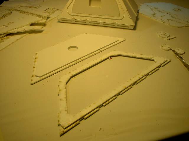
 aafp16.jpg The side pieces have a light ly scribed line to help lineup the detail pieces |
 aafp17.jpg Detail pieces added on. The hole is for the knob ot take of the side piece if that option was used |
 aafp18.jpg Another view |
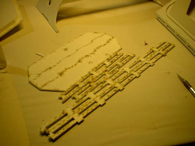
 aafp19.jpg The detail strips. These are provided in styrene to complete the foot shell but the builder an leave it as is or later replace them with real aluminum piefces. The edges shold be bevelled as per the blueprints to be more accurate or left as is. |
 aafp20.jpg One piece has been glued on |
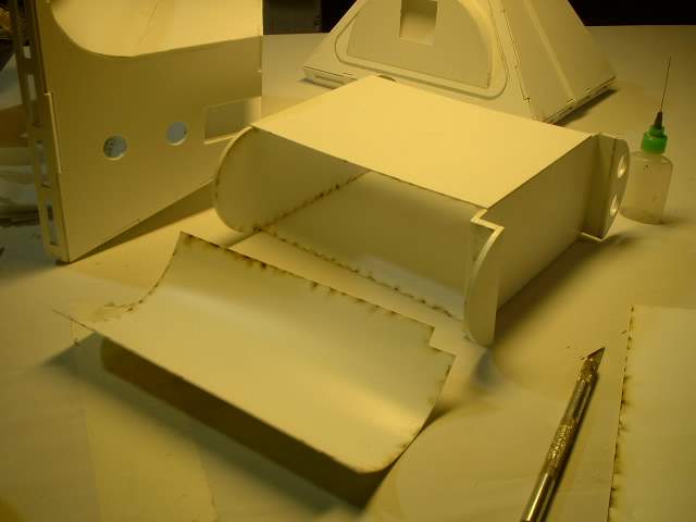
 aafp57.jpg Next are the battery box ends that will be glued together |
 aafp58.jpg |
 aafp59.jpg |
 aafp60.jpg To make sure they are glued together correctly use the back piece as a guide to make sure it is correct length |
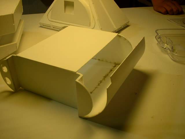
 aafp61.jpg Overall view |
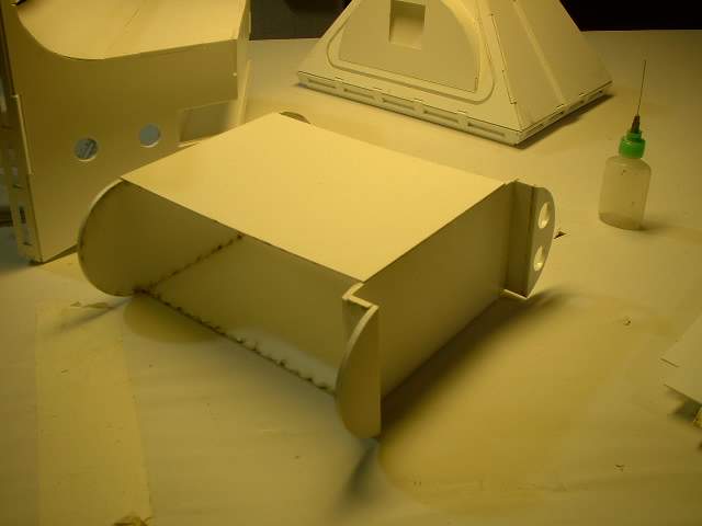 aafp62.jpg I thought this assembly sequence would be the easiest method but it is not. The curved sections shold be glued on first. |
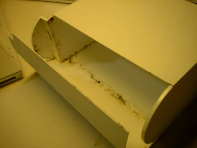
 aafp63.jpg Pretty close up pictures but again work on the end pieces first as this method meant my end curved pieces was too short on one side and too long on the other. No guides are provided for locating the side pieces so I eyeballed it and I was out by only fraction of inches and it is enough to throw the alignment out |
 aafp64.jpg |
 aafp65.jpg |
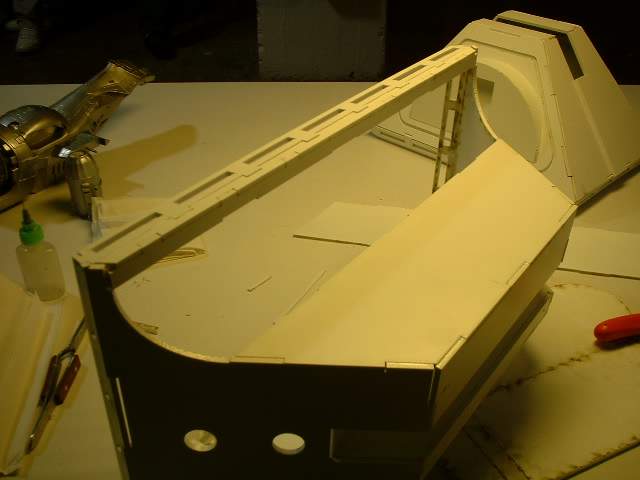
 aafp66.jpg Attempt one to glue the curved piece by bending it as much as I can. I could never get enough bend so i started to slowly glue the curved part a section at a time |
 aafp67.jpg cloe up of inner braces from scrap styrene that should be added later to strengthen the joint |
 aafp68.jpg |
 aafp69.jpg Here is my (at the time ) brilliant idea on how to get the curved section I needed. I taped several pop can section together |
 aafp70.jpg I then clamped one of th eend pieces to the pop cans so they wold not move |
 aafp71.jpg Close up of second clamp |
 aafp72.jpg Baked at 300F and this is the result. |
 aafp73.jpg Unfortunately the edges are slightly curled and the piece shrunk so it is useless |
 aafp74.jpg |
 aafp75.jpg |
 aafp76.jpg Well now lets scribe lines on the inside to make bending easier |
 aafp77.jpg |
 aafp78.jpg |
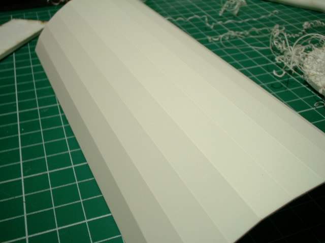 aafp79.jpg Curved but doesn't look great. I wold need to add putty to teh inside and then sand teh outside to get a nice curved finish. |
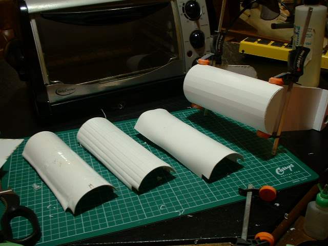 aafp80.jpg Ok so left to right |