A&A Frame and 3rd leg drop design idea - Jan 4 2006
In the quest for a low cost solution for a 3rd leg drop system I have been looking at some drawer slides. I found some heavy duty ones at Lee Valley tools (Part No 02K3012 12" 100lb Full Extension). Preliminary CAD work and measurements showed there maybe a problem with fitting it into the frame area and that the drawer slide may have to extend up into the dome area.
I decided to wait until I got the middle leg assembly to test it in the frame.
The solution I came up with has it's down sides but looks promising. The drawer slides are relatively cheap and I was thinking to make it as strong as possible I could use 4 of these slides for the 3rd leg drop system.
My final solution was to cut off about 2 inches from the end of the largest section. We still get the needed travel but there is a danger of the ball bearings falling out under certain situations from the middle track. This can happen if the frame is upside down. One solution is to modify the end to prevent this. An easy solution that I can illustrate later.
I have an idea for the motor system to drop the 3rd leg which was discovered by Craig Smith. He used an automotive power window system. Look for an update later at my attempt to install this system
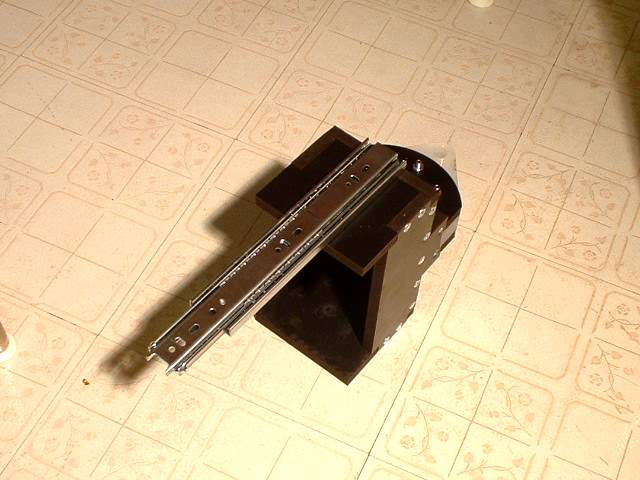
Here is the modified drawer slide installed on the A&A middle leg
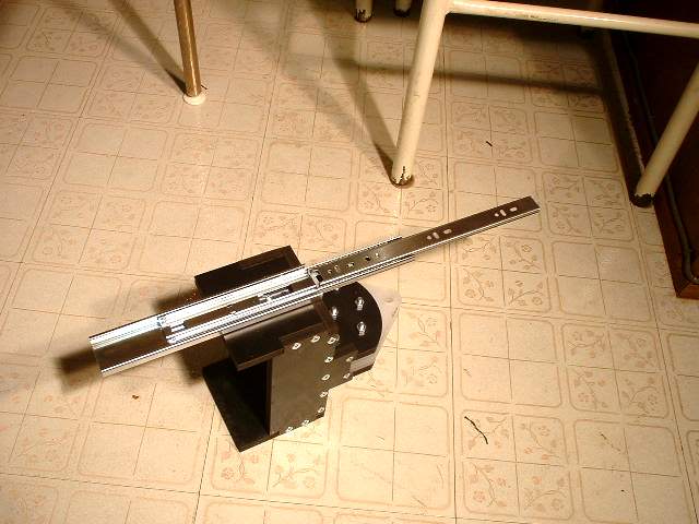
Here is it extended. Note that in this configuration the 3rd leg is retracted. The added benefit is that the drawer slide is retracted with the 3rd leg extended which also makes it stronger for transferring loads from the middle leg to the frame
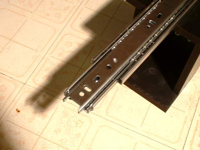
The modified end
edge view
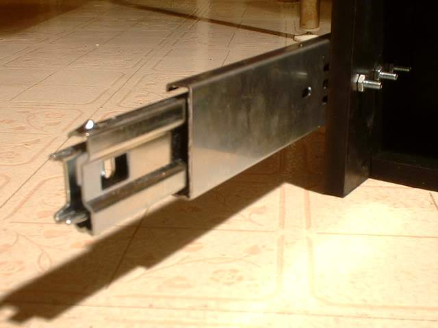
End view. On the original drawer slide you would not be able to see the inner tracks
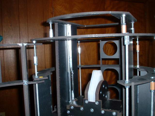
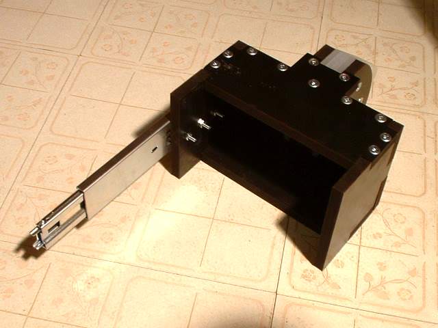
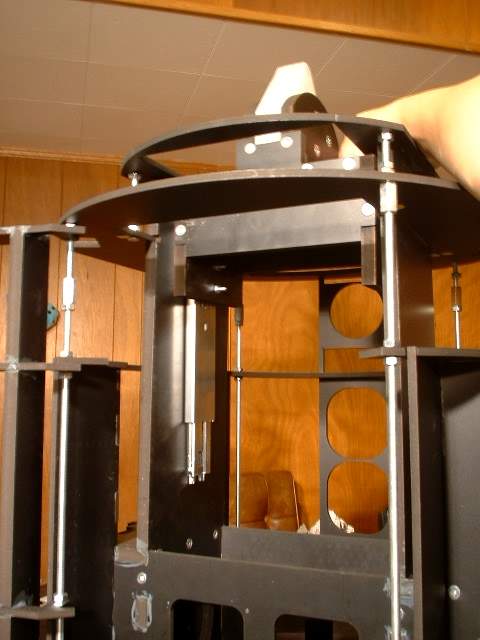
Installed in the frame. This was one reason the A&A frame was designed with the large inner cavity and the 2 side walls where linear bearings or slides can be easily mounted
A slightly different angle
From a low angle
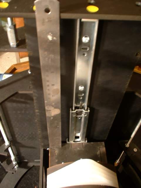
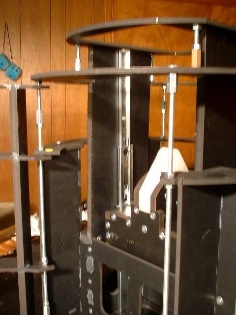
From above with a ruler attached. Some drawings show you need 9 inches of travel while I have worked out around 10.5 inches to fully retract the middle leg and ball caster. The ball caster I have drops about half an inch when lifted off the ground. Here the ruler shows we can get 12 inches of travel if the upper part of the track goes to the top of the frame. However that can introduce other problems
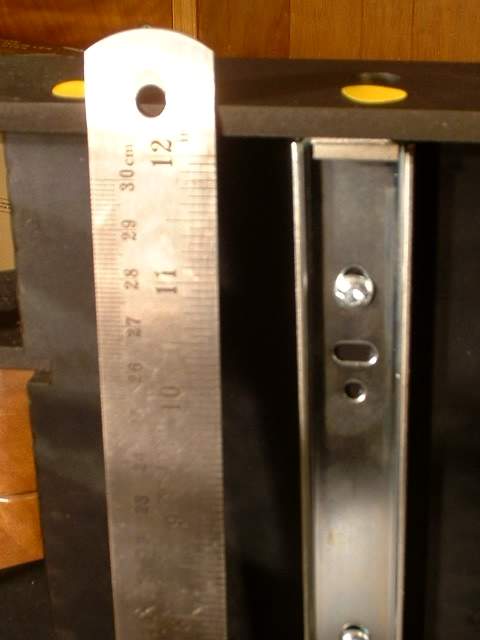
Yup that's a 12
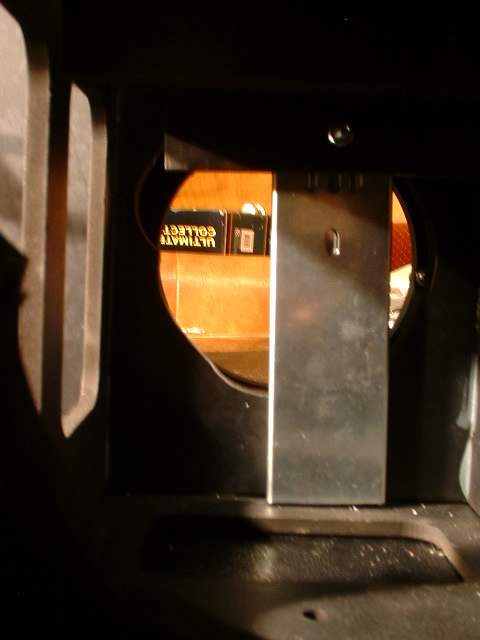
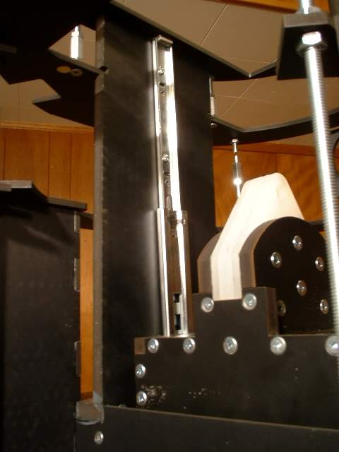
At the bottom (top) the drawer slide covers part of the Satellite motor opening. There may be interference issues. Installation and removal of the motor is not a problem as the drawer slide is out of the way then the 3rd leg is deployed.
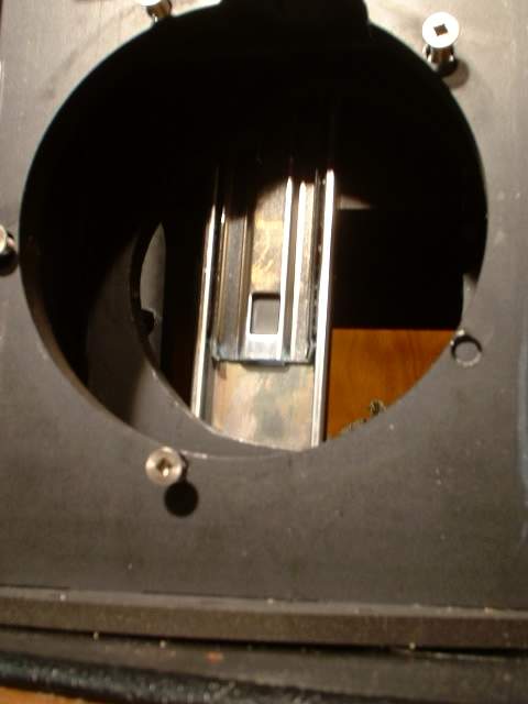
I centered the slider on the middle leg but it can be moved to one side to make room for the satellite motor
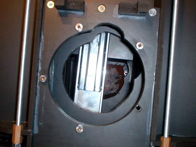
Same view with flash
3rd leg deployed
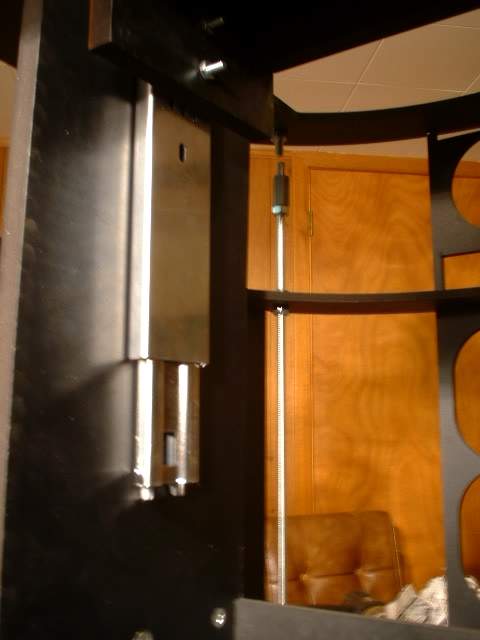
Close up of the drawer slide. The fact that the drawer slide is retracted makes for a stronger assembly when the 3rd leg is deployed
The bottom of the 3rd leg is flush against the bottom ring of the frame. If more travel is needed the ring will have to be opened up for clearance. This will depend on other factors such as leg length, 3 legged mode angle etc.
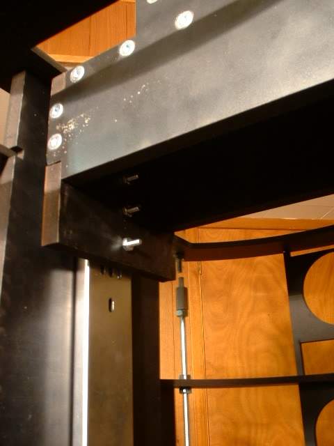
Top view. There is not as much ankle housing area. This was done to minimize the distance that forces have t travel from the middle leg to the frame. A larger leg assembly was also harder to fit into the frame space.