Adding Switches to the 12CH RF Remote
Sept 10 2005
A lot of people are using the CF Sound II and the relatively low priced 12CH RF remotes. There was concern that if there were 2 droids using the same remote at the same location then there would be interference. This would be true if the builder did not change the standard channel in the transmitter and receiver codes that come wit the unit when first purchased. This is shown on another part of my web site.
What I am going to show you is how to use one remote but have multiple receivers. In my situation I have 2 receivers for a total of 24 functions I can control. One receiver is used to control 12 sound channels of the CFII. I could install another receiver to use the other 12 channels of the CFII. However my second receiver is going to be used to control various gadgets in R2. All I have now is a bright light inside one or the HPs but I would like to open panels, add the periscope, light saber launcher etc.
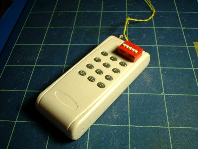
I have used a dip switch to change between the two receivers. In theory if I had enough dip switches I could keep adding receivers to my droid. Since I have only 2 boards I need to control only 2 channels. This can be done using a simple toggle switch but I have kept my options open for the future.
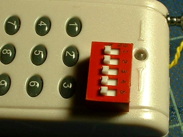
This is a close up of the switch mounted to the remote. To location was determined by where I had space inside the remote so that it would not interfere with anything. You can purchase these from most electronic stores. They come in numbers as low as 2 up to over 12. For complete control of all codes you would need two 8 switch units.
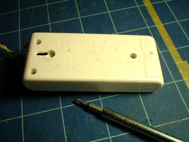
Now we get ready to open the remote by removing the 3 screws
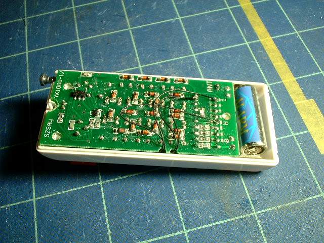
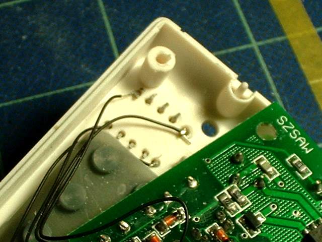
Opened up. Notice the black wires I have added. This wire was purchased from an electronics store and is fairly fine (32ga?)
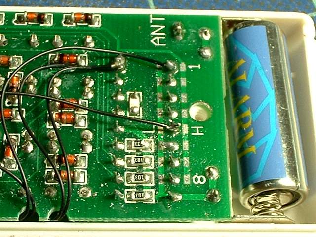
A close up showing the wires soldered to the contacts for choosing the channels
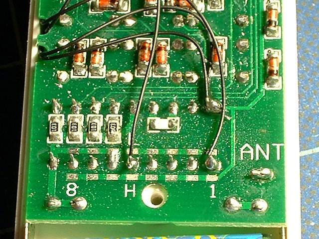
Another view. The top two right wires are doubled for safety and is connected to a location that is the same as the bottom row of the channel choices. This location was just easier to solder to. The other wires were chosen to match the receivers I had already soldered up
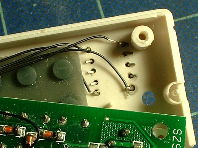
A close up of the switch showing the ends of the switch have been wired up and the rest of the pins bent over to hold the dip switch unit on the remote case. A small hand drill was used to drill the holes for mounting the dip switch. When choosing a dip switch try and get one that you can easily change with your finger.

The routing of the wires
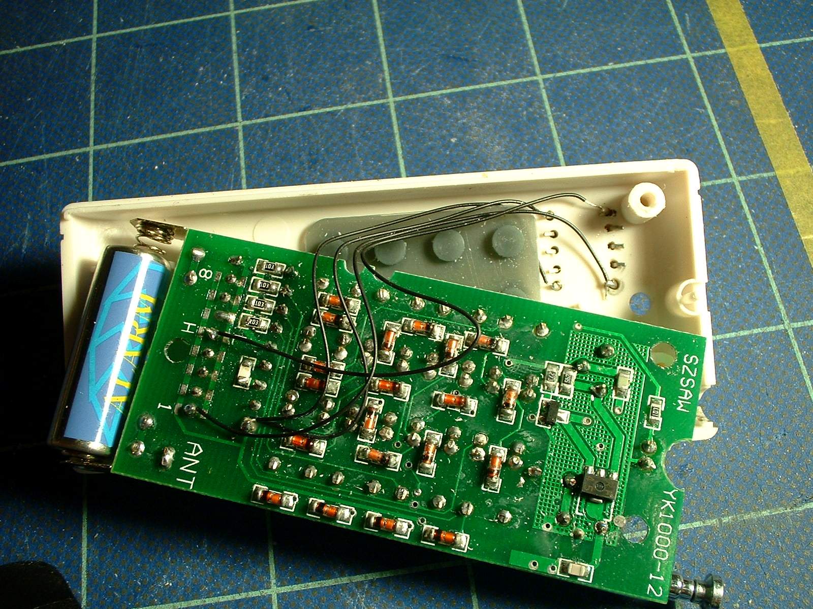
Since I am controlling 2 switches in theory I can control 4 boards (off-off, off-on, on-off, on-on). If you have only one switch you can control 2 boards maximum. This is a bigger picture so that hopefully thing will be clearer
Another close up of the back of the dip switch wiring.