
12Ch RF Remote
This is the 12 Channel Radio Frequency Remote quite a few people have been getting to control various items in their droid.
This is information from the people I got the remote from
http://www.lightobject.com/Support/RF12CH.htm
Basic Operation for 12 Channel Remote Control Module:
Operating Voltage: 12V DC.
Each channel's relay has three pins for connection: 1, 2, and 3.
1) Pin 1 & Pin 2 = Normally Open circuit.
2) Pin 3 & Pin 2 = Normally Closed circuit.
There is a jumper (labeled "J13") can be closed or opened to select one of the following two modes:
1) When the jumper is on, it is in Latch Mode.
2) When the jumper is removed, it is in Momentary Mode.
*Note when power to the system is interrupted, all latched states is reset.
*There is also a RESET button to manually reset all Latched states.
Encode/Decode:
On receiver board there is a Decoding IC chip, 2272M4, and inside the remote control there is an Encoding IC Chip, 2262M4. This set of IC Chips can be used to encode your remote signals so if more than one remote system are placed close together, they won't interfere each other. You only need to do little soldering work on Pin #1 through Pin #8 of both chips to bring out the Encode/Decode function of your remote system. Connection on both IC Chips MUST match otherwise the remote and the receiver module can not talk to each other. There are {3 to the power 8} =
6561 different combinations for encoding/decoding, isn't it cool?On the back of the board there should be labels like:
" L" -------- Stands for Low digital state.
" H" ------- Stands for High digital state.
" 1" -------- Indicates this is Pin #1.
" 8" -------- Indicates this is Pin #8.
Just in case there aren't any labels printed on the PCB board, you still can easily figure out the "L" and "H" states yourself: After power is hooked up to the system, use a Voltmeter to measure the contacts on both sides of the column of eight pins. Voltage level on each side should be consistence. If one side is "H", the other side should be "L". To figure out Pin #1, look at the front of 2272 or 2262 IC Chip. Pin #1 is the first pin on the left side of the dent. You don't have to connect all eight pins to High or Low, even only one pin to H or L will do the encoding/decoding.
Here are some pictures of how I set my code
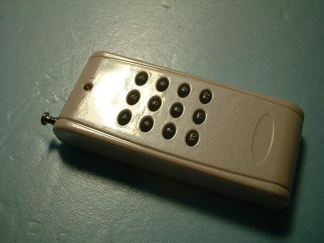
The 2 parts that you get. The left part is the receiver while the item with the buttons is the remote (transmitter). You should first test the unit by hooking 12VDC to the receiver and then pushing each button on the remote. You should hear a click noise coming from the receiver. This means it is working.
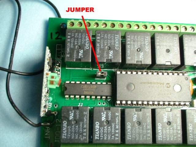
This jumper sets the board to on/off and to momentary on. If you want a light to go on and stay on leave the jumper in. If you only want a momentary signal such as to operate some other system this is what you want.

This is the reset button. If you have set your board to momentary and you want the board to be reset to on/off this is the button you push. Also marked is the terminal for the power supply.
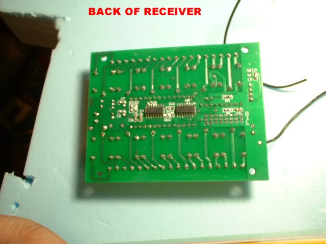
The back side
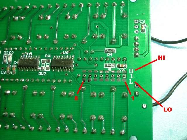
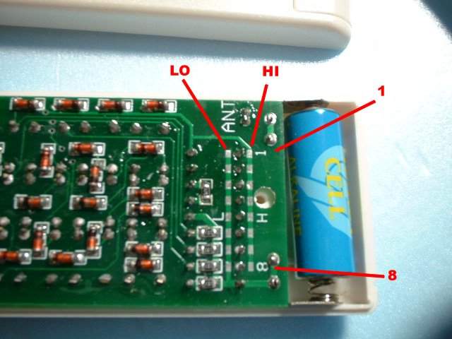
Here is the Hi and Lo banks for the encoding. Also from right to left are the 1-8 terminals. By connecting these terminals you can get over 6561 different combinations. What we are going to do here is to solder only one terminal. We are going to join Hi-6 together. If we wanted we could join any number of others to get the different combinations
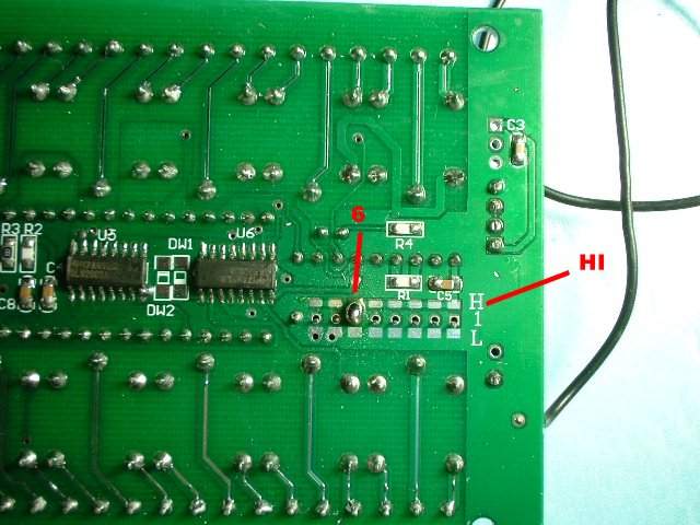
Here we have joined the middle pin with the Hi-6 tab. That is all you have to do here
Now time for the remote (transmitter)
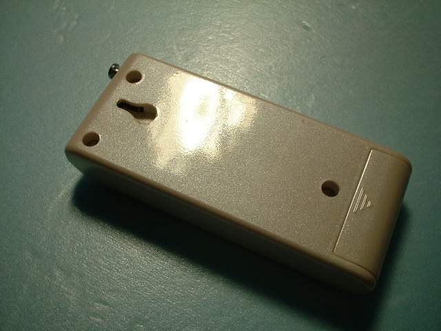
The back
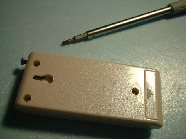
You will need a tool to get to the screws to gain access to the insides
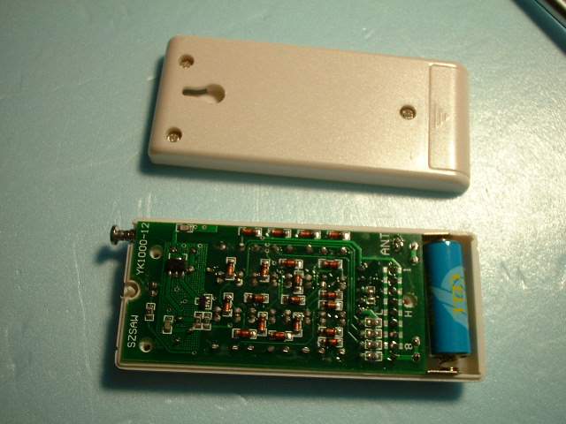
The Insides
Just like on the receiver we have a Hi and Lo bank and 1-8 terminals
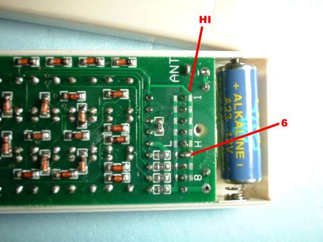
And here we have the middle terminal joined with the Hi-6 junction. The next step is to put the cover back on and then power up the receiver board and test every button to confirm that it works.

All done and I have labeled the remote H-6 so I know it is for this specific board which I have also labeled on the side.
Note: The lower left corner is relay 1. The lower right relay is relay 6. The upper right relay is relay 7. The upper left relay is relay 12. You can see my marks on the board. This will be helpful when wiring things up later on.
NOTE: In theory you could have 6561 of these boards inside your droid and 6561 remotes. If you had 2-3 boards inside your droid to perform various functions you will need 2-3 remotes. But if you get the right switch and with some wiring you can have only ONE remote to handle and a switch that can change between the different receivers in your droid. Neat eh?
Sept 6, 2012