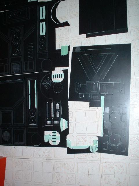
 0501.jpg The parts are pulled from the lower right section of the skins |
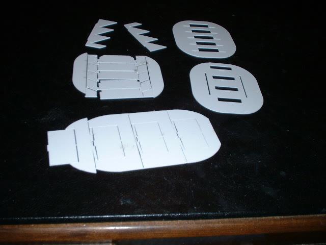 0502.jpg All the parts ready to go |
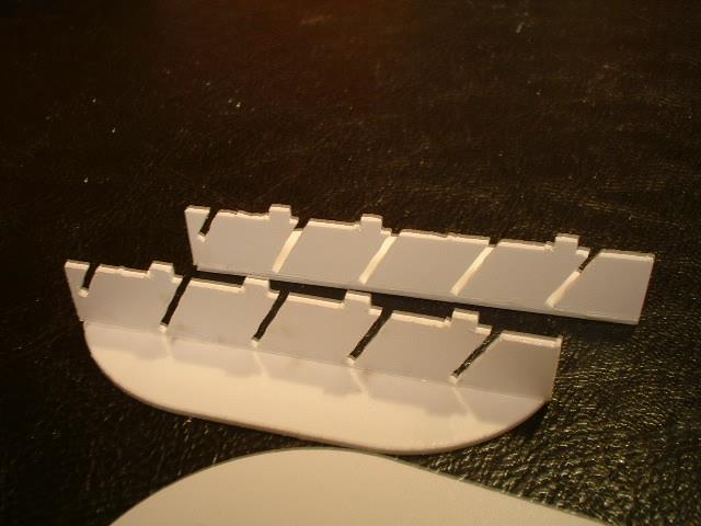
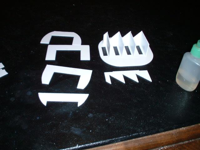 0503.jpg Here ar the parts for the upper vent. One side piece (zig zag shaped) and the top pieces have been glued together already. When dry the other zig zag piece is to be installed. |
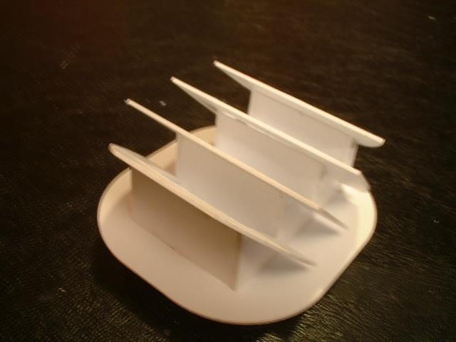
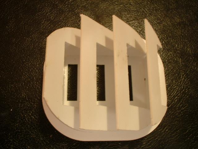 0504.jpg Next is all the top pieces. The three parts to the left slide int oslots. The final right piece rests on top of the zig zag piece and the front is flush with the edge of the zig zag piece |
 0505.jpg Here is a better view of the last piece glued to the edge of the last zig zag part |
 0506.jpg |
 0507.jpg |
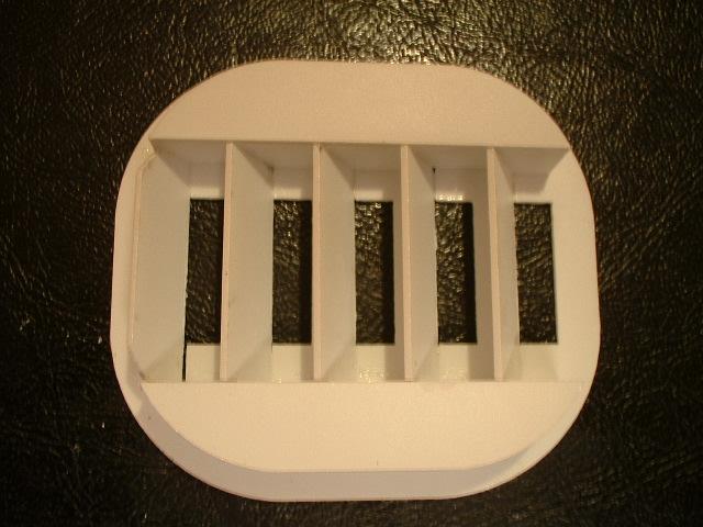
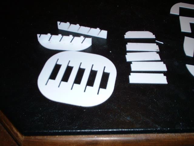 0508.jpg Here ar the parts for the lower vent. WARNIG: the piece with eh angles slots is very fragile. The ones I had were broken in multiple pieces. With careful assembly it should be no problem |
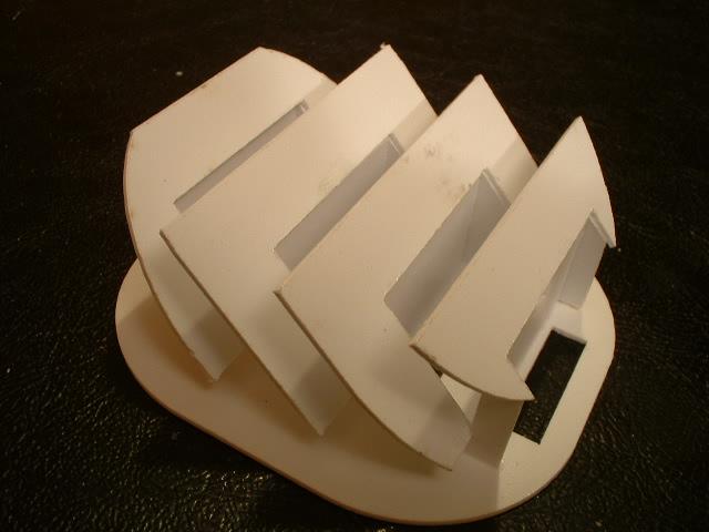
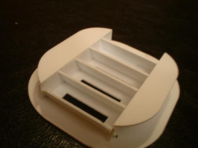
 0509.jpg This is wha tthe parts look like assembled. withsome care and patience |
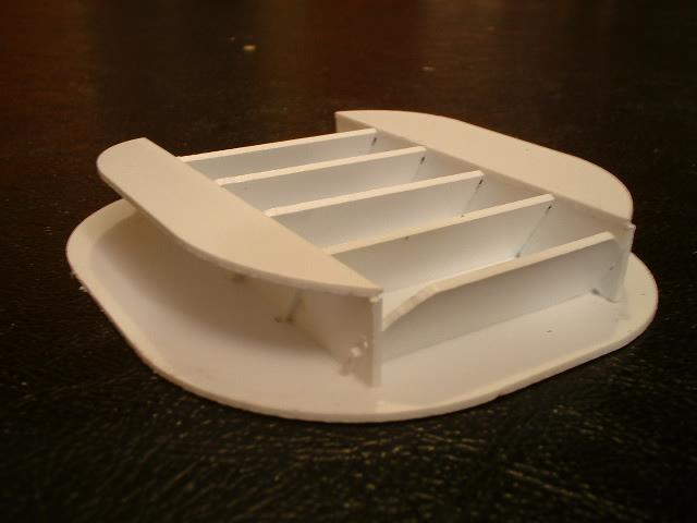 0510.jpg Side view of the assembled part |
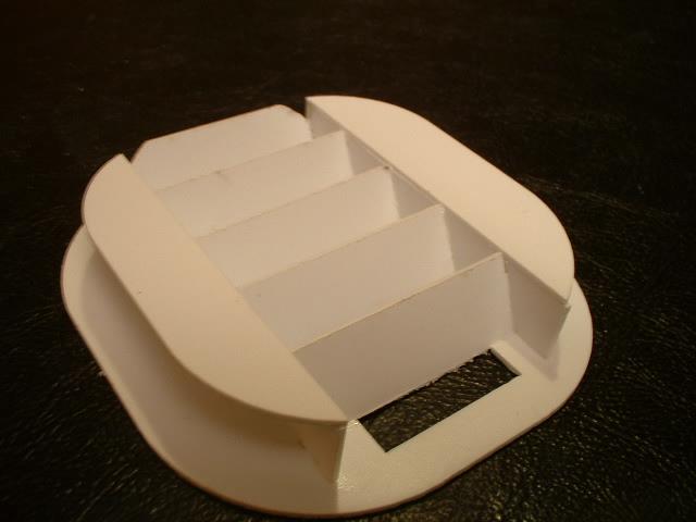 0511.jpg One side sectoin is glued on and left to dry. the slots of the side piece are to match up with the slots on teh back piece. Make sure the part is square with the backplate. Once this has dried you can start installing the top angled slats |
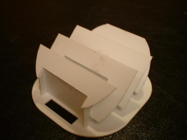
 0512.jpg Note that the outer top part is toped compared to teh back piece. Don;'t make the mistake I did and mount it backwards to that the assembly was off top. |
 0513.jpg |
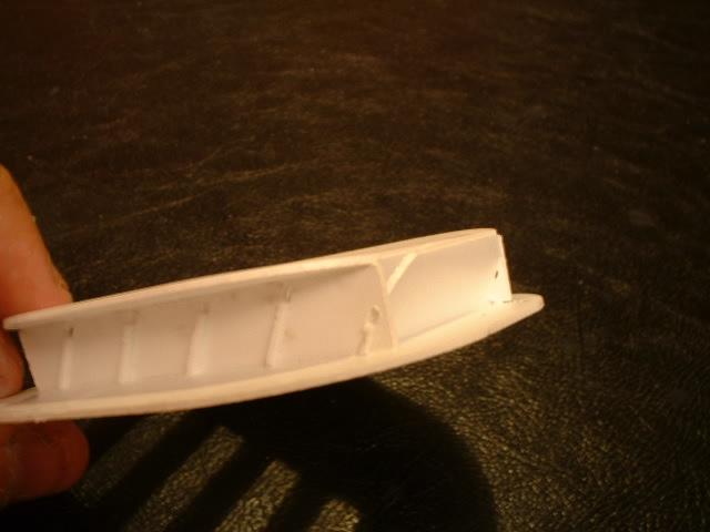 0514.jpg Edge view |