R2s Reverse Gear
Sept 7 2003
With the design of the feet the left and right foot have the same layout for the motor. This means that when driving forward one motor is rotating forward while the one in the other foot is rotating backwards. When rotating backwards the motor is not as efficient and is slower. This means R2 does not drive straight but it drives to the left. In order to go straight I have to slow down the motor that is rotating quicker to the same speed of the motor that is slower. This reduces the top speed of my R2. I looked at several methods so that both motors are rotating forward while driving forward.
1. Repositioning the motor so it drives forward. This turned out to be a harder problem then I thought due to the limited space in the foot shell. Even taking out the 12V gel cell battery there was not a configuration I could use.
2. Bring the drive shaft out the back of the gearbox and reverse the mounting of the motor. Again space to do this killed the idea. The gearbox of the motor would stick outside the battery box, a new motor mount would need to be made, some sort of bearing would need to be installed to deal with the shaft forces.
3. Putting new gears into gearbox so that the rotation goes in the desired direction. I could not find any off the shelf parts that I could use to do this task. I would have to replace 2 gears in the gearbox. Not impossible but the costs would be high.
I also have a goal to try and make it as cost efficient as possible so that other builders can use the same technique.
Below is my first attempt at the project. The idea is to put in a couple of gears in a little bracket to reverse the direction. In the end there were some problems but they will be explained.
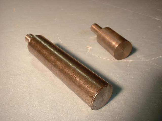
Here are the drive shafts. The one on the left is the existing one with the far end turned down so that it will accept the new gear being added. The item to the right is the new shaft added.

Here are all the parts that will go into the new assembly. The gear to the left was pulled from the existing feet assembly. The gear at the bottom was purchased. The aluminum square is a 2x2 tube. No bushings were used. Hopefully this is not a problem. If it is I will look at putting bearings in. I did not originally design in bearings or bushings due to the tight spaces.
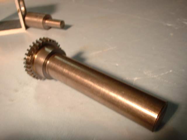
Here is the existing shaft with the new gear added. When I ordered the new gears I thought that they already had set screws in them. Well surprise they didn't so I had to drill and tap the hubs and get some set screws. So when ordering them make sure they have the set screws already in them.
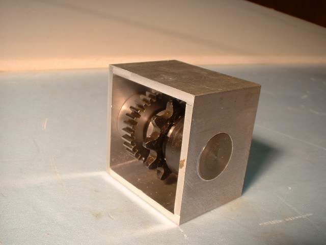
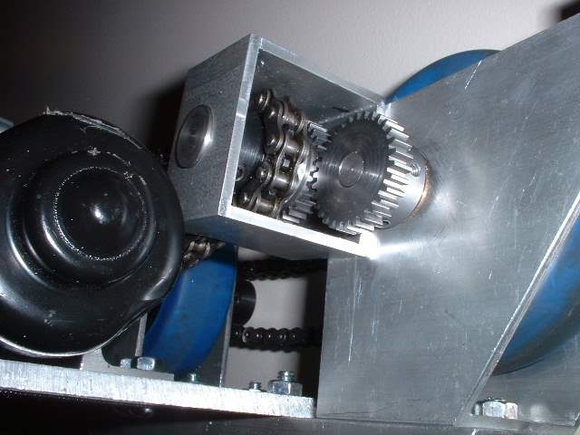
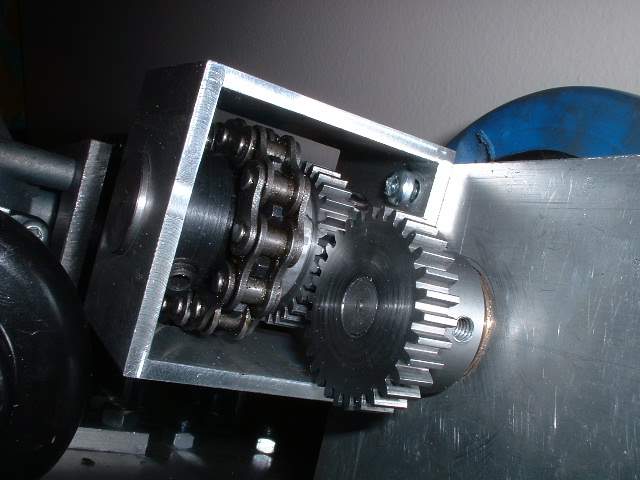
Here is the assembly all together. Now the sprocket is very close to the top and bottom of the aluminum tube. Later on I had to mill out some of the sides to let the chain clear.
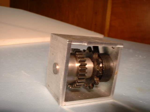
Another View

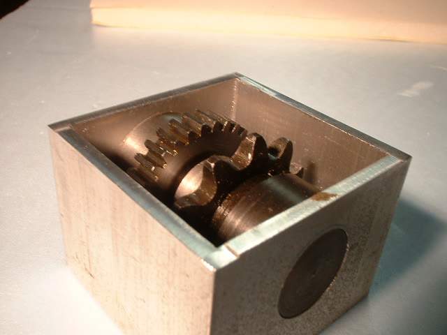

Here you can see how little clearance the sprocket has
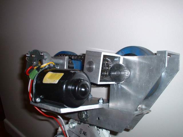
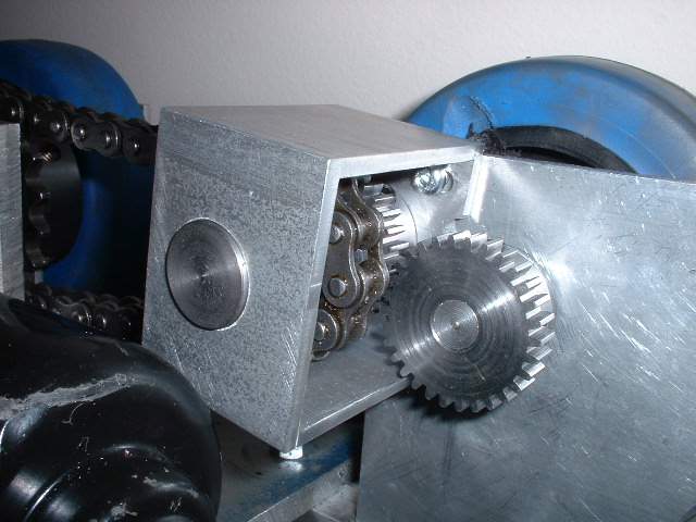
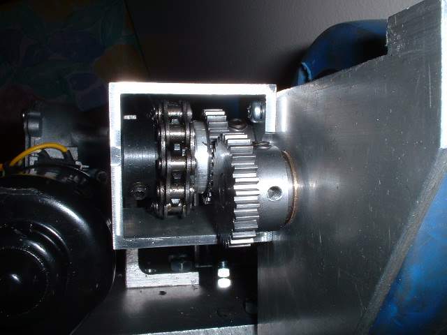
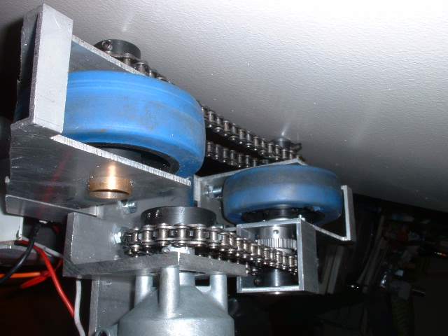
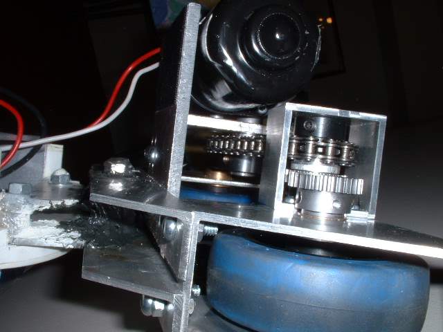
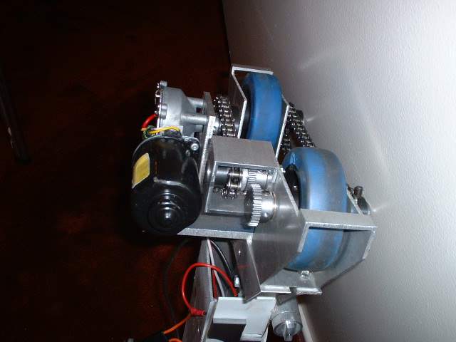
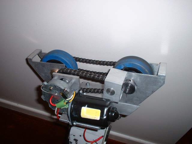
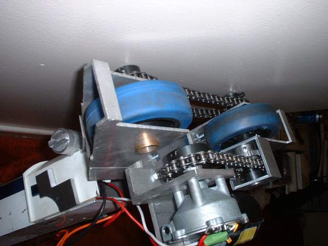
The next batch of pictures are various views of the assembly installed
There are 2 screws that hold the assembly to the foot bracket. The holes in the 2x2 tube are slotted to allow some adjustment to make sure the gears are meshing right.
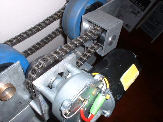
With the new assemble I had to cut down the drive chain and the chain on the far side. This means that all 4 chains I have are different lengths.
It turns out that the assembly was not attached low enough on the foot bracket. This mean the top left of the tube in this picture hits the motor. To make it clear I had to move the motor out a bit to get things to fit. This might affect the foot shell and battery box assembly. I will deal with those later.


Well I have done some tests and the results are encouraging but I ran into a few problems.
1. On the first test one of the new gears slipped on the shaft and jammed against the housing.
2. The set screws on one of the wheels did not hold. Tightening them did not help. I will have to redrill and tap the set screws. This limited the running I could do as the other wheel was not touching the ground. At first I did not understand why only one wheel was touching the ground as when I set it up I was sure that I had both wheel touching. My conclusion was that I had 2 different wheels and they had slightly different diameters. Enough to cause this difference. So with one wheel not touching the ground and the other with the stripped set screws the whole assembly would not move.
3. A couple of times the assembly appeared to jam. I am not sure what caused the problem but I did notice that the motor was putting a lot of strain on my new assembly. Having the sprocket on the side it is was actually bending the bracket.
Conclusion
The assembly does work but I think it can be better. I now plan to reverse the gears positions so that the sprocket is close to the foot bracket. Any large forces would not produce the bending forces I witnessed. This means I will have to make a couple of new mounting holes and I will need a new drive shaft that is longer to bring the gear out. Stay tuned
Oct 2003
Well I modified the assembly to reverse the location of the gear. After testing I have found that there is still considerable bending of the frame causing the gears to grind. I believe that the adjustment slots I put in there were what is causing the problem. The large forces are pulling the assembly back just enough to cause the problems. There is nothing worse than to hear gears grind. When the system was working I did notice that the left side was still slower. I am now wondering if the motor itself is slow.
About a week after thinking about this problem and trying to solve the problem it did occur to me that I can just put in a sprocket with more teeth. This would take the motor output and alter the speed so hopefully the left and right side spin at the same speed. The down side is that the motor will be working harder to keep up the same speed as the other side. One very simple solution. At this point I do not know which number of teeth would work best so I am getting gears with several different number teeth.
Nov 2004
While revising my web page I came upon this page and realized that this page is no longer relevant to my drive system. Later on I have managed to convert the Saturn motors to 24V and this solved the problem of the uneven speeds. I have decided to leave this section up to show the troubles I have gone through to try and get more speed out of the drive system.
If you want to build your own R2 go here --http://groups.yahoo.com/group/r2builders
or here --http://movies.groups.yahoo.com/group/astromechs
for an R7 go here --http://movies.groups.yahoo.com/group/r7droidbuilders
Email me ask@interlog.com