New R2 Frame
August 2, 2003
Here are some images of my latest frame. I have not had a chance to test anything yet so i don't know if the thing will even work. Here is a step by step process of items added to make up the frame. The main base of the frame is a linear actuator that a member of the R2 Builders group was offering.
The frame was drawn out on a CAD system to try and eliminate as many mistakes as possible.
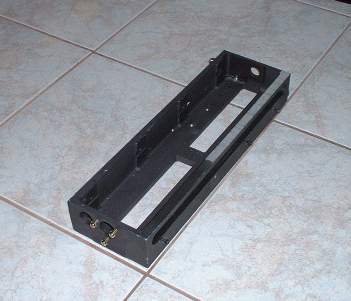
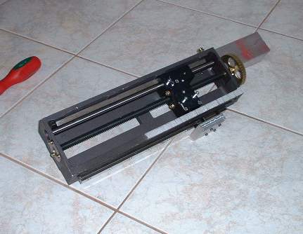
The dark chunk is the basic frame of the actuator. I have pulled off the motor as well as the gear and bearings. I don't want the metal shavings to drop all over the place from all the drilling and tapping.
The 2x2 aluminum square tubing has been screwed to the frame by drilling and tapping into the frame. This allows me to disassemble the frame if needed. The 2x2 is one of the main frame supports
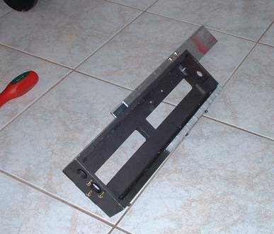
Here is the assembly flipped over. It will be better to see the parts added to the frame from this side.
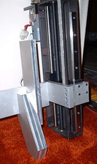
I have now put back the linear gear and the block that rides on the gear. One gear for the belted motor has been put back on and can be seen at the top of the actuator. The motor has not been put on yet.
On the bottom side a linear bearing has been attached to the side of the actuator. The plan is to have this actuator take some of the loads that the middle foot sees instead of all the forces going through the actuator.
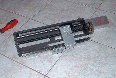
An aluminum piece has been screwed to the travelling carriage of the actuator. This will be screwed to the side linear bearing to allow load transfer.
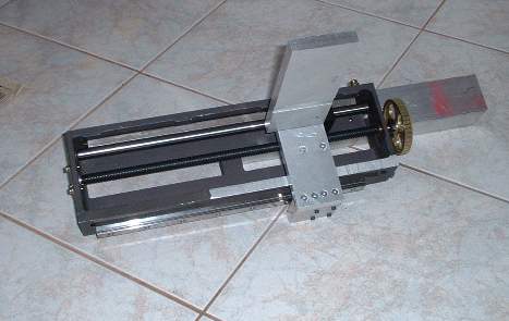
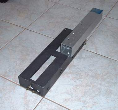
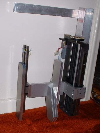
The main chunk of aluminum has been added to the carriage. From here the middle leg assembly and J-bar assembly will mount
A bit of a jump but now we see that a second carriage is on the left side of the main leg plate. There are 2 linear bearings on that side. This was done so that loads can transfer to both sides of the frame. A 1x2 square aluminum tube has been added to the first 2x2 tube. Another 2x2 tube will parallel the first one. The specific build sequence was done to try and make sure that parts are lined up and that the bearings will not bind as they travel up and down.
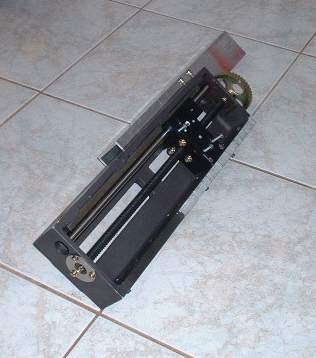
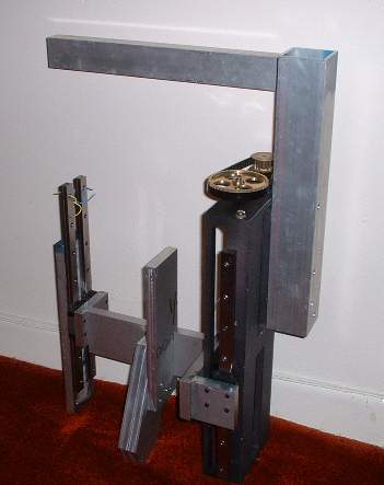
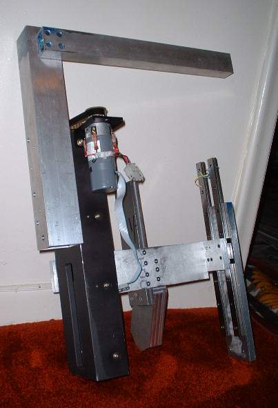
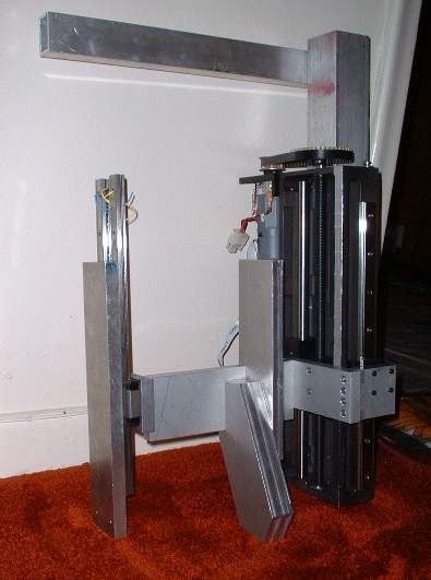
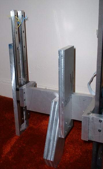
The following are various angles of the frame so far
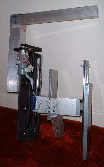
This is a close up of the middle leg. The 1 inch thick plate is where the middle leg ball caster will be screwed into. The plate that goes up is where the J-bar will be riding against.
If you want to build your own R2 go here --http://groups.yahoo.com/group/r2builders
or here --http://movies.groups.yahoo.com/group/astromechs
for an R7 go here --http://movies.groups.yahoo.com/group/r7droidbuilders
Email me ask@interlog.com