R2 FEET DRIVE SYSTEM - Installation Instructions
April 18 2003 Rev 0
If there are any questions email either Heath Macmillan (HMacmill@rjcyr.com) or Alex Kung (ask@interlog.com) or both.
Your first step is to inventory all your part to make sure you have received everything that should be included in the kit.
Each Kit Includes the following:
|
Part No |
Qty |
Description |
Other |
Check |
|
1 |
4 |
Wheel Brackets |
Aluminum |
|
|
2 |
2 |
Main Body Plate |
Aluminum |
|
|
3 |
2 |
Motor Bracket |
Aluminum |
|
|
4 |
2 |
Ankle Brackets - threaded |
Aluminum |
|
|
5 |
2 |
Ankle Brackets - 5/8" hole |
Aluminum |
|
|
6 |
8 |
Brass bushings |
Already pressed into wheel brackets |
|
|
7 |
2 |
Short Drive Shafts |
|
|
|
8 |
2 |
Long Drive Shafts |
|
|
|
9 |
32 |
1/4-20 x 5/8" Flat Head Socket Cap Screw (FHSCS) |
|
|
|
10 |
16 |
1/4-20 hex nuts |
|
|
|
11 |
6 |
M6x1.0 x 16mm SHCS |
For Saturn Motor mounting |
|
|
12 |
2 |
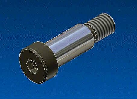
Shoulder Screw, 5/8" x 1 1/4" |
For Ankle pivot point |
|
|
13 |
2 |
Shaft adapters |
Custom made to fit Saturn motor |
|
|
14 |
2 |
1/8" x 3/4" roll pins |
Drilled at assembly |
|
There are items that need to be purchased by the builder to complete the assembly. The list below includes samples suppliers and part numbers of where to purchase these items. The parts are standard items and should be available from local suppliers at a cheaper price than most Internet sources.
Items needed to be purchased by the end user to finish the feet assembly
|
Part No |
Qty |
Description |
Other |
|
A |
4 |
Wheel 4in Dia. 3/4" Bore 0.92" Roller width 0.5 Hub Width |
Example: McMaster-Carr Part No 2474K49 (Neoprene 80A Durometer), Part No 2474K19 (Neoprene 60A Durometer), Part No 2475K19 (Urethane 60A Durometer) part No 2475K49 (Urethane 80A Durometer) |
|
B |
10ft |
Chain #35 chain 3/8 Pitch (RC35) |
Part No 7210K1) |
|
C |
4 |
#35 Chain connectors |
Only 2 needed if 2 wheel drive is chosen Part No 7210K125 ) |
|
D |
2 |
Sprocket 1 For #35 Chain 3/8" Pitch 18 Teeth 3/4" Bore (RC35B18T c/w 3/4" bore and set screws) |
Part No 6280K121 ) |
|
E |
6 |
Sprocket 2 For #35 Chain 3/8" Pitch 11 Teeth 3/4" Bore (RC35B11T c/w 3/4" bore and set screws) |
Only 2 needed if 2 wheel drive is chosen Part No 6280K113 ) |
|
F |
2 |
12VDC Saturn Wiper Motor |
Motor - 12 VDC worm gear drive motor has high and low speeds. High speed is 106 RPM at 12vdc, 4A and low speed is 41 RPM at 12VDC, .91A. Lots of torque. A 2.25" offset is attached to the 3/8" threaded shaft. The offset has a universal joint on one end. Fits 2000 -2001 Saturn "L" Series cars. |
Note: Alex Kung has purchased a 4in dia wheel in a fixed caster and taken apart the assembly to use the wheel in one of the test rigs. The hub area had the correct diameter needed for the drive shafts as well as enough material that a hole could be drilled and tapped for a set screw. Although this is a lot cheaper than purchasing a wheel that is listed above, there is no long term test report on how this setup will function over time. The hub area on the test wheel was plastic and it is not know if this may crack over time due to the stresses it encounters. This is FYI in case someone else wanted a different route for the drive wheels.
Features:
Two wheel or 4 wheel drive is an option
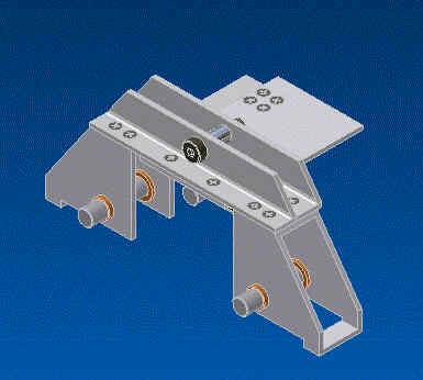
Fig 1
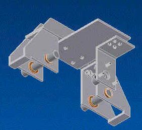
Fig 2
Here are two isometric views of the completed assembly with the parts that are included in the feet kit. The assembly order will be slightly different, as it will be shown. The main reason for the difference is to install the motor and gears.
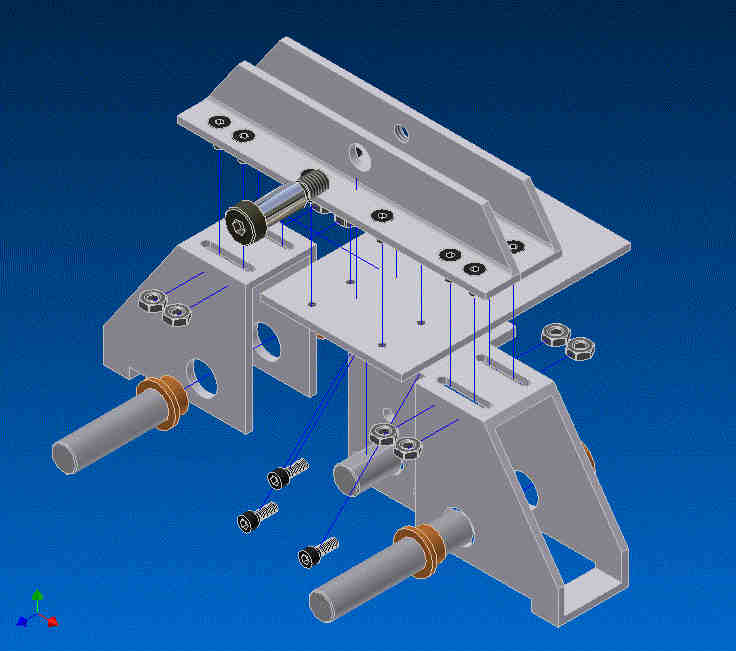
Fig 3
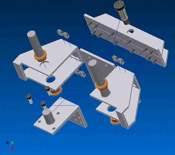
Fig 4
Here are two different exploded views of the parts included in the feet kit and their locations. This has been included to help you visualize where all the parts will be located.
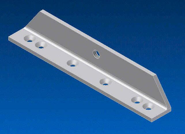
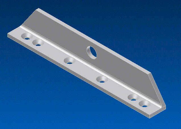
Fig 5 - Ankle Bracket - threaded Fig 6 - Ankle bracket 5/8" hole
First we start off with two of the angles. Note that one has a threaded hole in the vertical leg and the other one has a larger hole. This is for the shoulder screw.
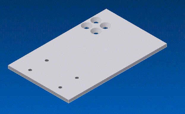
Fig 7 - Main Body Plate
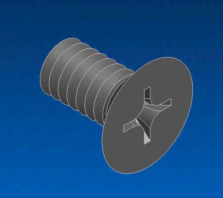
1/4-20 Flat Head Shoulder Screw
Attach the Ankle Bracket - threaded to the Main Body Plate
with the 1/4"-20 Flat Head screws (2) Next attach the
Ankle Bracket - 5/8" hole to the Main Body Plate. You can install the Shoulder Screw now if you want.
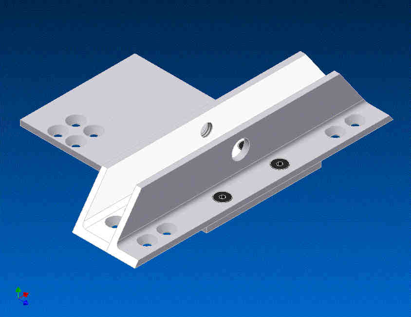
Fig 8 - Assembly No 1
Here is what your first assembly should look like with out the shoulder screw. You should have 2 of these assemblies
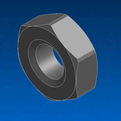
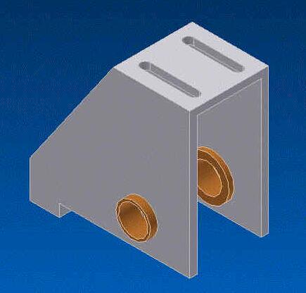
Fig 9 - Wheel Bracket
Next you want to install the two Wheel Brackets to the ends of the Ankle Brackets. Refer to the main assembly drawing to show the orientation. Each wheel bracket is installed with 4 nuts and bolts. These can be left loose for adjustment later.
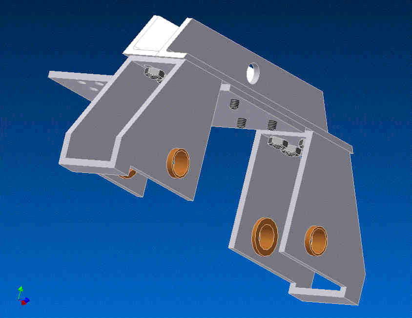
Fig 10 - This is what your assembly should look like now
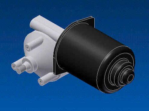
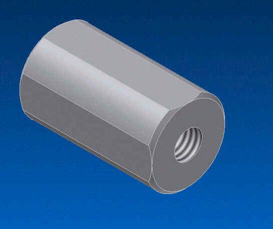
Fig 11 - Saturn Motor Fig 12 - Shaft Adapter
Next screw the shaft adapter to the Saturn motor. Drill a hole into the motor shaft and install the 1/8" x 3/4" roll pin.
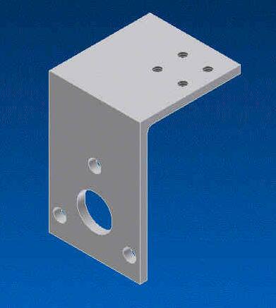
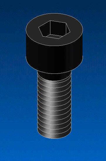
Fig 13 - Motor Bracket SHCS
Mount the motor to the bracket using the M6x1.0 x 16mm SHCS (3 per motor)
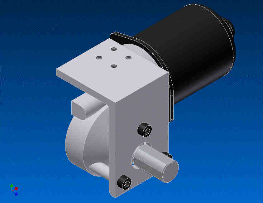
Fig 14 - Mount the motor so that the 4 screw holes are above the motor.
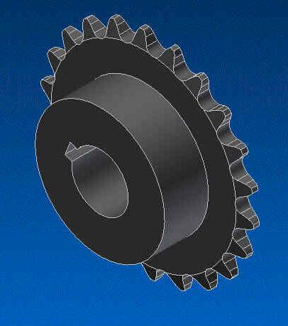
Fig 15 - Next install the 18 toothed sprocket loosely to the shaft adaptor. The set screws will line up with the flat
spots on the shaft. Later on we will tighten the set screws.
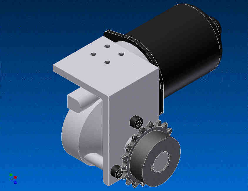
Fig 16 - Motor assembly with sprocket
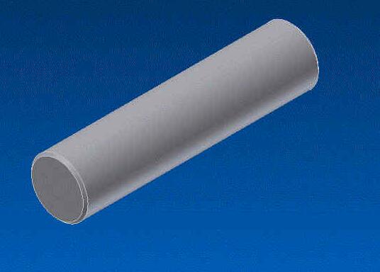
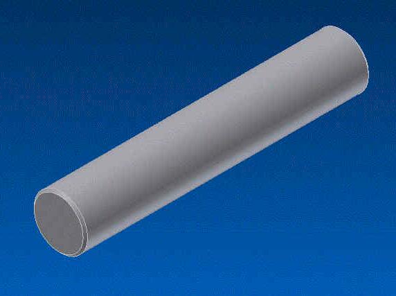
Fig 17 - Short Shaft Fig 18 - Long Shaft
Next install the two shafts and wheels to the wheel brackets and mount the motor to the main bracket. Note that there is a short and a long shaft. Install the short shaft opposite the motor sprocket.
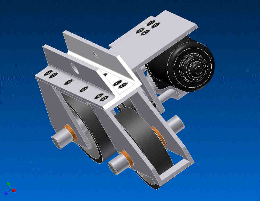
Fig 19 - This is what the assembly should look like at the moment Note that the short shaft does not go through while the long shaft is centered on the bracket.
If there is some slack in the wheel hub so it can go from side to side align the wheels with the end farthest away from the motor. Tighten the set screws on the wheels.
Note: Depending on the wheel you have purchased there is a possibility that there may be some interference between the wheel hub and the bronze bushings. If this is the case you will have to grind or file down the bushing to get it to fit.
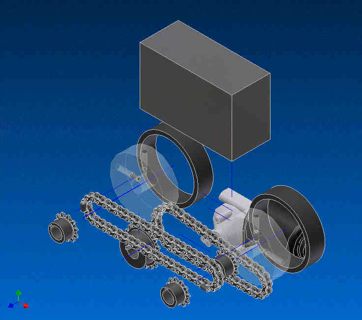
Fig 20 - Items that are not included on the feet kit. The big rectangular grey object is a 12VDC 7.2A gel cell battery
Fig 21
These two drawings show the location of every item in the final assembly. This will give you a clearer idea of where the motor, chain and different size sprockets go.
The wheels shown are the custom made ones by Heath. Heath made these wheels himself to show that it is possible for a cheaper alternative.
Here is a link to a PDF file of Heath's wheel design - Click Me
April 18 2003 - Here is a link to a tutorial on how I made my wheels - Click Me
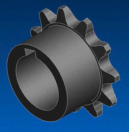
Fig 22 - Next install the 11 toothed sprocket to the 3 shaft locations. On the outside shafts if the sprockets are as tight up to the bushing as possible this will prevent the shaft from wandering from side to side as it rotates. This will also keep the chain lined up when it is moving.
On the inner shaft line up the sprockets with the one on the motor. The chain will take some misalignment but the more straight it is the less loss of power and the less likely the items may wear out over time.
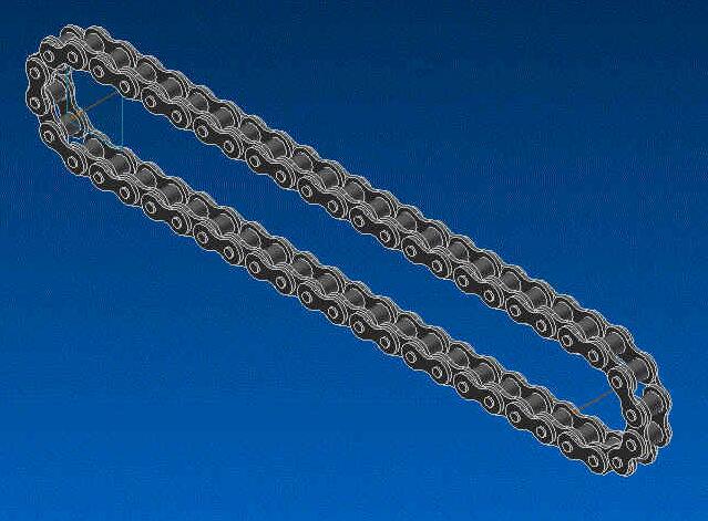
Fig 23
The next step is to make the chains for the drive system. First push the wheel bracket with the two sprockets as close to the motor sprocket as possible. Measure a chain length that will be long enough to fit over both sprockets. Cut the chain and join.
There should be enough slack in the chain and assembly to easily slip the chain on. Next slide the wheel bracket away from the motor sprocket until the chain is relatively tight. There should be some slack in the chain and the wheel bracket side should be parallel with the Ankle angles. Tighten the bolts on the wheel bracket.
You can make a second chain for the other motor assembly.
Next you will be making the chain for the outside sprockets. Again slide the wheel bracket as close as possible to the middle of the foot and measure the chain needed. Repeat the process of tightening the chain and making sure the bracket is parallel with the ankle angles.
For those who have never cut and joined chain before here is a quick tutorial. - Click Me

Fig 24 - Here are two views of the completed assembly
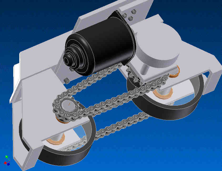
Fig 25
You have now completed the assembly process for the feet kits.
You should not run the motor forwards and backwards to see that there is no binding and that the chains are rotating freely and are parallel to each other. Hook up the white and yellow wires to a 12VDC power source. Test the assembly in one direction and then in the reverse direction. Adjust as needed.
For those who want to try a 2 wheel drive system they can leave off the second set of chains. It is advisable to install the second set of sprockets to help trap the shaft and not allow it to shift when they are rotating.
FAQ
Q. Will this assembly work with my Gary Weaver Feet?
A. The feet were designed to the compleat drawings for the feet, they should work with Gary's feet. Note that Gary's battery boxes and feet will have to be modified to get our frame to fit in. There is no designed mounting method to mount Gary's feet to the frame assembly. Also the ankle mounting for the assembly has a 5/8" diameter shaft.
Q. Will this work with a 2-3-2 system?
A. The 2 wheels per foot was designed to be put into a 2-3-2 system. The wheels were spaced as far apart as possible in the feet to try and gain the best stability in 2 legged mode. No provisions for a tilt system have been designed into the feet.
Q. Can I change the gearing from what you have specified
A. You can change the gearing to whatever you want. We have tried testing with a 28 tooth primary gear and an 11 teeth secondary gear but this appears to have overstrained the motors. We have only tested with the 18 and 11 teeth gears and know that these work well. Different gearing should give more torque or more speed but we do not know how they would work.
Q. Why are both wheels driven? (4WD) Would not the assembly be cheaper with only one wheel driven? (2WD)
A. There was concern that having both wheels driven (4WD) there would be very high forces when the assembly tried to turn. We have not encountered these problems during testing. It was also shown that the rig is slightly faster with only one wheel driven (2WD) but we also found out that there were instances on uneven pavement where the rig would high side itself. The four-wheel drive (4WD) eliminated this. If the R2 Builders is confidant that all surfaces being run on is fairly flat they could drive only one wheel (2WD). Later on the Builder can switch to the four-wheel drive (4WD) option if they want.
Q. The ground clearance of the frame does not look very high.
A. The wheel frames were produced that way to save money on manufacturing. We realize that this compromised the ground clearance. If the R2 builders needs more ground clearance they can easily modify the brackets. Instructions for modifying the brackets are available on request.
Q. Why did you not design your feet so both motors run in the same direction when going forwards or backwards? Then this would eliminate the problem of the assembly not tracking straight.
A. The feet were designed this way so that the left and right feet assemblies are the same. This standardizes parts and makes the assembly cheaper.
Q. The motor appears fairly low in the assembly and is very close to the ground. Why is it not higher?
A. We realize the motor is low. It was positioned to allow a 12VDC 7.2AH gel cell battery into the battery box. This helps to lower the center of gravity of the unit and makes it more stable.
Q. How do I tighten the chains?
A. The wheel brackets are slotted to allow for the chains to be tightened.
Q. How easy is maintenance on the assembly?
A. By going with standard gears, chains and motors it is hoped that replacement of items would be no problem. We have tried to make assembly and maintenance as easy as possible but there are always limitations.
Q. Can I fit bigger wheels in this assembly to get more speed?
A. No
Q. Will other motors fit in this assembly
A. It may be possible but we cannot guarantee if other motors would fit or not.
Q. What else do I need to get my R2 running.
A. You will still need the batteries and some sort of speed controllers. For his test rig Heath did wire up the power from the battery to the motors directly and ran his test rig with switches.
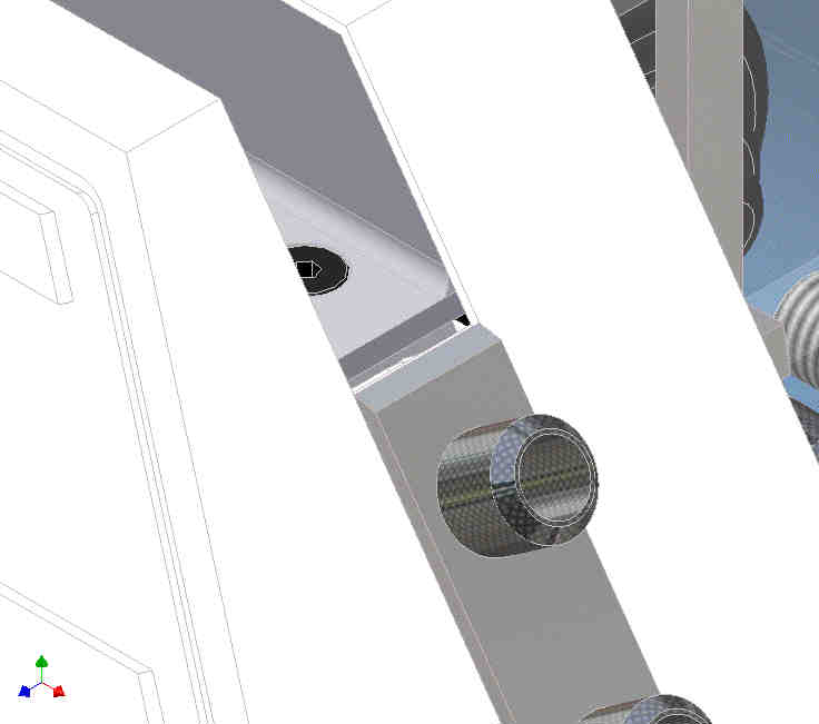
Fig 26
Note: The inner raceway of the ankle is formed by the inside of the foot assembly. To allow for manufacturing tolerances there is a small gap between the foot assembly and the foot shell as seen above. Depending on the builder they may want to leave this as is or close off this area.
This will be present for those that have Gary Weavers aluminum foot shells.
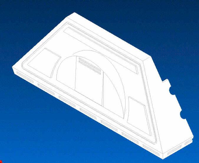
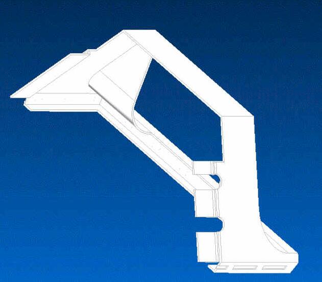
Fig 27 Fig 28
For those that do not have Gary Weaver's Foot shells here is an idea that Heath and I were thinking of for foot shells. This method uses Velcro to assemble the shell halves. The ease of disassembly will allow quick access to the feet area for servicing if needed.
To mount the foot shells Heath has added angles to the top of the foot assemblies for the foot shells to rest on. These angles were epoxied on.
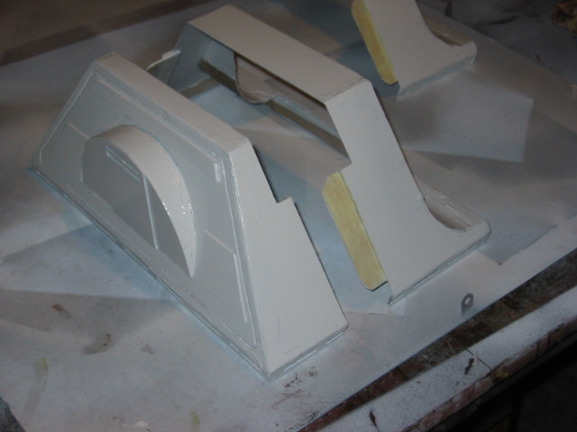
Fig 29 - Here are the feet shells that Heath made for his R2
Fig 30 - To mount his feet shells Heath glued on a couple of angle brackets to the top of the feet assembly. This gives the shells something to rest on.
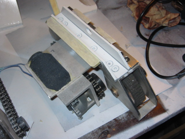
Fig 31 - Here the inside of the ankle raceway has been painted white. You can use Velcro to mount the foot shell and batteries.
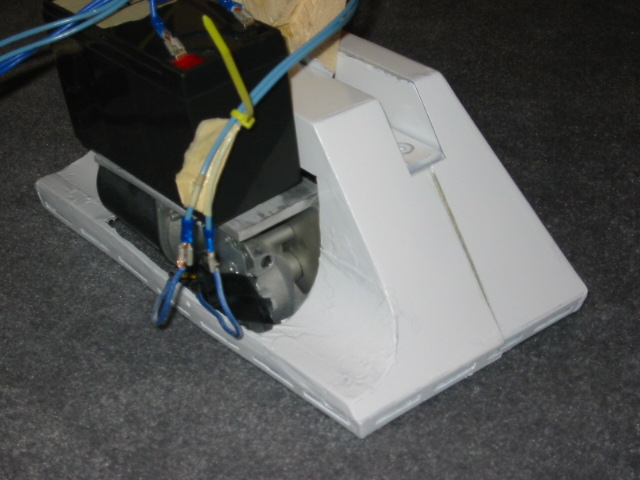
Fig 32
Here is the foot shells mounted to the feet assembly. Note the amount of area in the foot shell that has to be removed to fit the motor bracket in.
Renderings by Heath Macmillan
Designed by Heath Macmillan (Hmacmill @ rjcyr.com ) and Alexander Kung (ask @ interlog.com)
For other images of the prototype assembly please go to the following URLs