R2D2 2-3-2 Design Project
Feb 26 2003

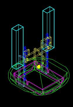
This is an isometric view of the body and the skirt that the frame will be in
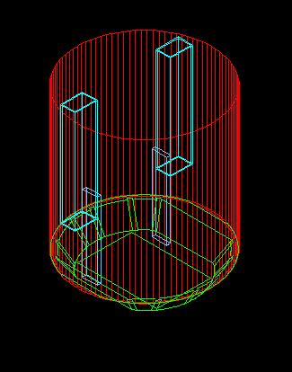
The main backbone of the design is the 2x4 square aluminum tubing (light blue). All forces will travel through these tubes. The slightly darker blue items are 1/2 inch aluminum plate. I wanted the aluminum tube to extend all the way to the bottom because I wanted an area to place batteries. These plates had to be used to create the needed area. These plate extend all the way to the bottom so that the body can stand by itself with no legs and all the weight is on the plates
To strengthen the skirt area there are plates (purple) that form a square on the bottom. This serves several purposes. 1. It spreads the weight of the body through the entire skirt area instead of only the two vertical 1/2 inch plate areas. So if the body was being put down slightly of to one side the plates would transmit the forces directly to the frame. The main reason for the plates is to provide support for the middle leg in 3 legged mode. This will be explained later. The square plates also helps to make the frame assembly more rigid.
Next are the linear bearings. Another member posted a site that had them on sale for $20US each. They are excellent value. After I got the bearing i found some great heavy duty drawer slides that would also have worked.
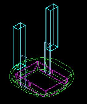
The yellow 1/2 inch aluminum plate is the frame for the middle foot system. It is attached to the linear bearings at 2 points.
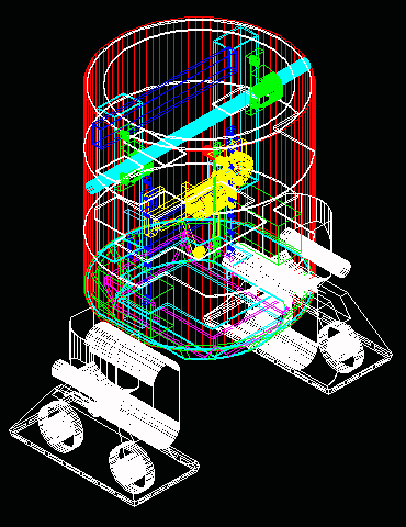
Here is the foot shell added (green)
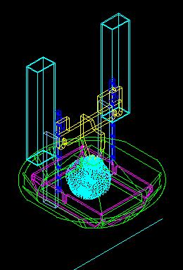
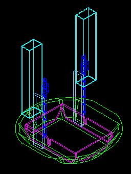
Here is the omni-wheel I am going to use. This is to give you an idea of the room taken up inside the body with the leg drop system. In the following images they will be removed so that the images will be clearer and hopefully easier to understand.
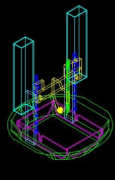
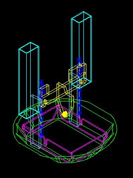
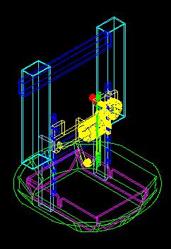
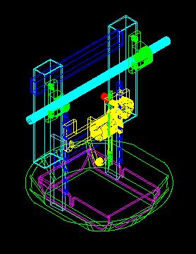
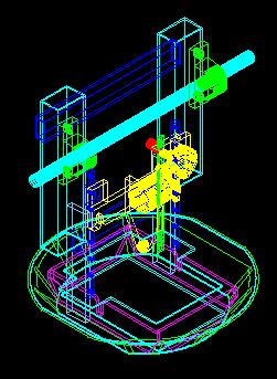
Next I have added a linear gear (Green) I am not sure what the correct name for the part is. I took it off of a car seat adjustment system. This was relatively cheap since I get 2 linear gears and the little matching gear.
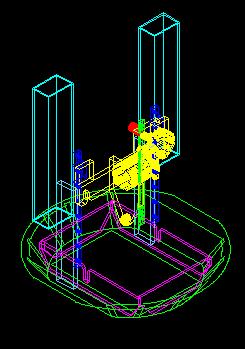
I have now added the Saturn motor (yellow) as well as the gear (red). I had a heck of a time placing the motor and linear gear In other layouts the motor is attached to the frame and the linear gear travels with the assembly. Reduces unsprung weight on the travelling assembly but this meant the linear gear height went almost to the top of the body. This meant I had to keep a part of the upper body open for this travelling gear. The other thing is the only location for the motor is at mid level or higher in the body. Of course this is not good for center of gravity. The body looks big but you quickly run out of room. Designing on the computer sure allows you to quickly look at different ideas. Now with the motor on the travelling assembly the weight that has to be moved is larger but the center of gravity will be lower in 3 legged mode.
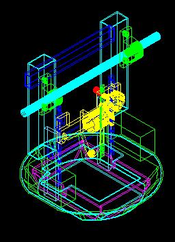
Next I have added 1x2 aluminum square tubing as cross supports. This is to make the frame more solid.
The 2x4 aluminum tube locations were determined by the pillow bearings that will be holding the cross rod for the 2-3-2 system. Here I have added the pillow bearings (green) and the 1 inch rod (light blue)
Now showing is the 0.125 inch aluminum plate near the bottom of the body. The bottom plates as well as the vertical ones are bolted to this plate to add rigidity to the frame. Another purpose for the plate is to attach the skin to the frame and as a platform for the 12VDC gel cell bateries.
Here is the location of the gel cell batteries. I plan on having 2 in the battery boxes and at least these two. The location of the batteries means I can put a door in the body so that I can remove and install the batteries relatively easily

Here are the other 3 rings added to the frame for rigidity and as attachment points for the skin. The location of the middle plates allows for the panels to be opened at a later date if desired.
And here is the body and feet added to the assembly. It can quickly get confusing with all the lines all over the place.
Hopefully this helps to explain what I am currently doing with my 2-3-2 design. If you are a bit confused just email me. At last count this is my 24th revision. Who knows if I am finished. Someone else may have a very good idea that makes me scrap this design.
As of this moment I still don't know if it will work. If you have any ideas or comments on my design so far I would like to hear them.
My next step is the mechanism to tilt the body the desired angle. I have looked at the J-bar system but am considering a different system. I have not ruled out the J-bar and think my frame can be modified to use this if my current idea does not work.
Once I get the body tilt system designed I will look at making a test frame to see if it will work.
Email me ask@interlog.com