R2-D2 Feb 2 2003
After designing and testing a new foot drive system with Heath I have decided to replace the existing feet system I had with the newer one. The benefits is that the speed will be a lot faster than the old system. The down side is that the motors are not as efficient as the old ones so the run time will be quite shorter.
At the same time I decided to modify the leg to shoulder mounting system to increase the strength. Before the shoulder area joining method was weak. This meant that I needed some ILM bars to make my frame strong enough. I wanted a stronger system because on several occasions the ILM bars broke and I was left high and dry. This new system should fix that.
Thirdly when I first was designing my frame I wanted to included a 2-3-2 system. The weakness of my shoulder area meant that this was not possible. The length of the middle leg beam could be a lot shorter. This was cut own to save weight and to give me more room inside to put more stuff.
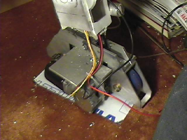
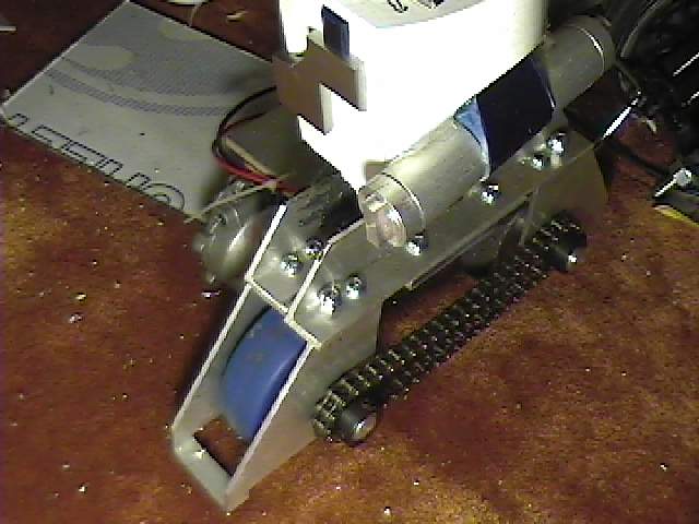
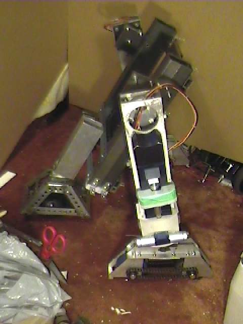
Here is the new feet assemblies installed on my R2
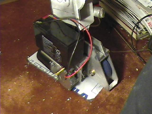
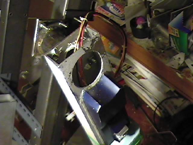
Here is a 12VDC 7.2AH gell cell battery included on the foot as designed. It will fit inside the battery box.
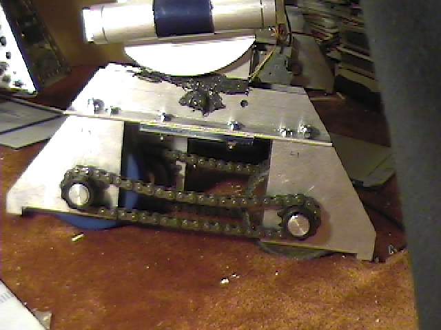
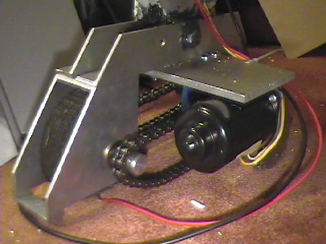
Side view of the assembly. Because my R2 is in permanent 3 legged mode I have epoxied the ankle area to make it solid. Past experience showed this to be necessary.
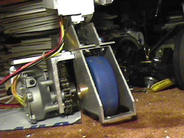
Another view of the feet assembly. Unfortunately my measuring was slightly off so that is why the ground clearance is low. The same goes for the motor.
I found the blue wheel at a surplus store and modified it to fit in my feet. I liked the colour and the fact that it is similar to R2's blue.
Outside view of the foot
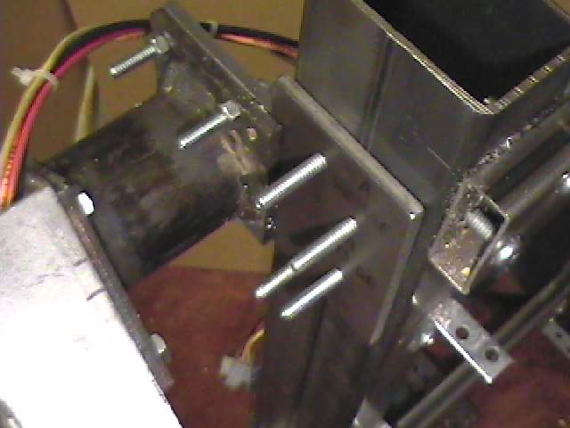
This is the new shoulder area. The shoulder hub is missing which allowed me easier acces to the bolts to mount my new flange to the leg.
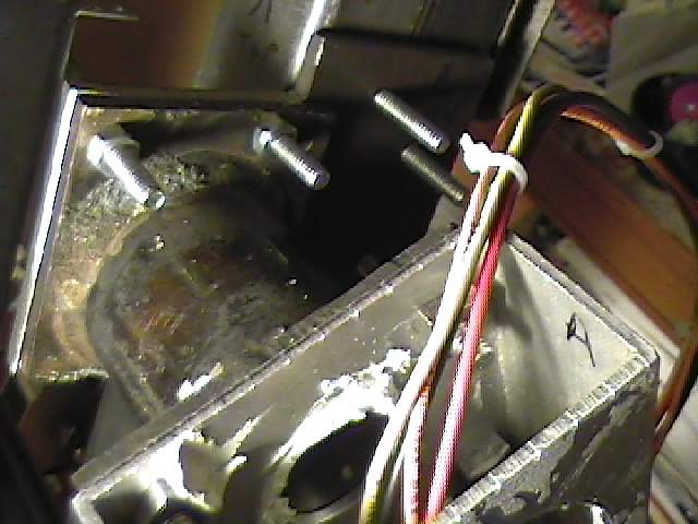
Close up of the new assembly. The two rear bolts are attaching a new plate to the existing frame. Due to limited space inside the body the plate was drilled and tapped. I don't think I could have reached in to get a nut onto the bolt.The two bolts on the left mount the plate to the leg flange. This is attahced with nuts and bolts. Bolts are a bit long here but I will use shorter ones later.
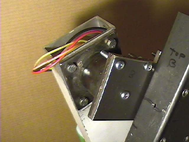
Here is the other side showing the back of the plate. I used only three bolts as this looked strong enough. Testing later showed this to be true.
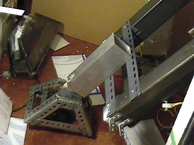
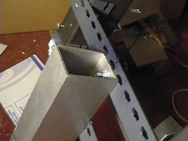
Here is the shortened aluminum 2x3 tubing. Before it was twice as long for the failed 2-3-2 system. The upper cross bar was moved down after the 2x3 was cut in half.
Close up of the leg shows the bolt used to mount the middle leg.
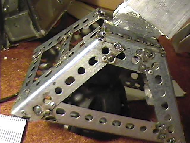
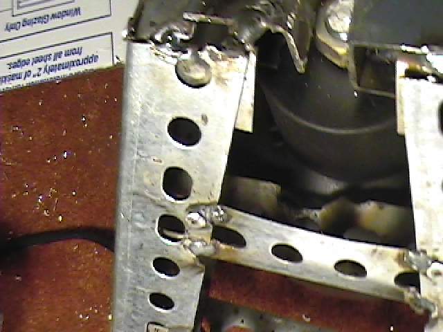
Here is the frame for the middle foot shell. It is made of shelving angle. It was all cut and riveted together before being tack welded for more strength. The middle shelf used to hold the old 2.5 inch OD caster was removed to make room for the new 4 inch OD ball caster. The 2.5 inch OD caster was the maximum size one I could fit inside the middle foot. The ball caster allowed for a larger diameter ball. This will allow R2 to navigate over bigger bumps that the 2.5 inch caster had problems with.
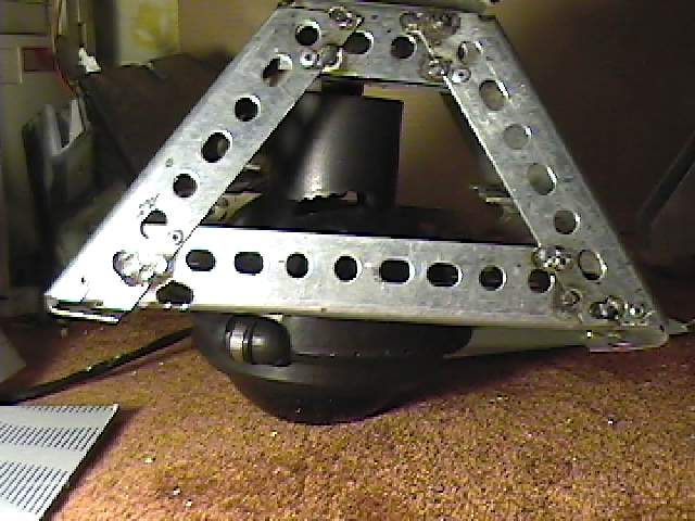
A better view of the ball caster
To mount the ball caster I had to modify the angle to be able to weld in a nut that the ball caster can screw into
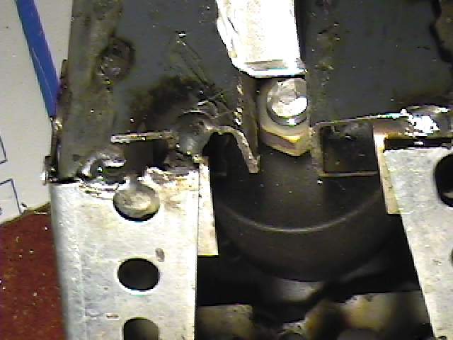
Another view
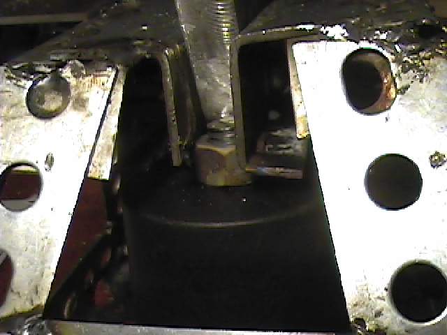
i also had to cut down the mounting screw on the caster since it was too long and it hit my 1/2 inch aluminum plate that acts as the ankle.
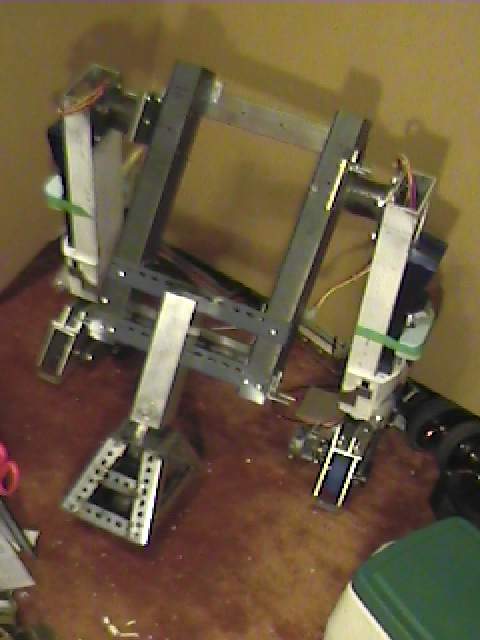
The new frame ready to go
Side view
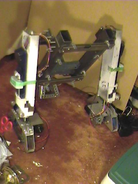
Rear view
Another close up of the new should mounting system
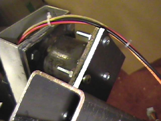
Now that the 12VDC batteries are in the battery box I have had to route wire up the leg. I use moulded plugs to make attaching and disassembly of R2 easier.
Another view of the feet. The red and black wires are the ones that are going to attach to the battery. I always leave enough wire when making assemblies. Nothing is more frustrating then being an inch to short.
Depending on time the next step would be to recover the feet with shells. I may use the old ones to scratch build new ones
If you want to build your own R2 go here --http://groups.yahoo.com/group/r2builders
or here --http://movies.groups.yahoo.com/group/astromechs
for an R7 go here --http://movies.groups.yahoo.com/group/r7droidbuilders
Email me ask@interlog.com