 jvn01.jpg Here are the two finished feet assemblies |
 jvn02.jpg A second view of the two feet assemblies |
 jvn03.jpg This is a close up of the angle brackets and the butchering I had to do to get the screws in. The problem was due to the fact that the design called for 0.1875" thick material and I used 0.25" thick material. Counter sunk screws will be the order of the day to give a clean finish in areas that people can see. |
 jvn04.jpg Side view showing the open architecture. Sorry fancy terms that mean we hope that maintenance will be easy if needed. Quotes for our initial designs was in the $350 range for a set so we quickly redesign the system to the present configuration. Hopefully it will be a LOT cheaper to manufacture. The two brackets that hole the wheels are slotted to allow for the chain to be tightened. |
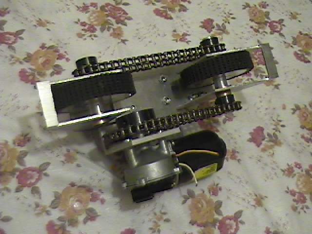 jvn05.jpg The bottom view with the Saturn motor mounted. |
 jvn06.jpg. |
 jvn07.jpg A close up of the wheel bracket. This wheel is custom made by Heath. It was also designed to fit a standard specified wheel |
 jvn08.jpg A close up of the main drive wheel. There may be a fit problem with the screw that holds the adapter shaft to the Saturn motor output shaft. |
 jvn09.jpg A second view. We will have to determine if this is a problem during testing. |
 jvn10.jpg To view showing the tightness of the components. It wasn't always easy to try and fit everything in and have the adjustability we wanted. |
 jvn11.jpg End view of the assembly. Some interference problems with the top of the wheel and the end of the bolts that mount the bracket to the frame. |
 jvn12.jpg The motor bracket |
 jvn13.jpg Another close up view showing the possible problems with the bolt lengths possible hitting the wheel |
 jvn14.jpg This is the other bracket using 0.125" thick angles whereas the previous one had a 0.25" thick angles. I am not confident with the strength of this material and will be using 0.1875" thick material in later versions. |
 jvn15.jpg Top view showing the placement of the bolts. |
 jvn16.jpg The second foot with the countersunk and round heads. |
 jvn17.jpg Side view showing the assembly and the custom wheels that Heath made |
 jvn18.jpg Another bottom view. |