Alex Kungs R2-D2 Foot Design
My ultimate goal is to design a second R2 that can do the 2-3-2 and haul around 200lbs of weight. My current R2 is in legged mode all the time and is not geared properly so the top end speed is quite slow.
This is the current design for my new foot mechanism. I am going with a chain drive using two 4 inch wheels. Each wheel will be driven with the motor source being a 12VDC Saturn motor.
Just to give you an idea of how long this process has taken I am now on my 16th drawing revision.
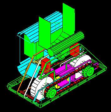
Here is the entire assembly with foot, battery box, ankle etc. It can be a bit confusing with everything in there. I will try and explain my concept in the following diagrams.
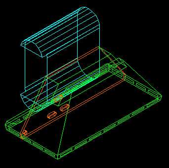
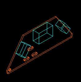
We start off with a wire frame of the foot, the battery box and the first mounting plate. The mounting plates will be either 0.25" thick plate of aluminum or carbon steel
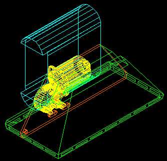
I have now added the wire frame of the Saturn motor. This is the location and mounted to the first plate. I have placed it low in the battery box so that I am able to put in a 12VDC 7AH gel cell in with it. The more weight as low as possible the better for the center of gravity for my R2-D2.
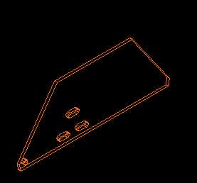
Here is the first mounting plate by itself. The three slots are the adjustment for the motor to make sure the chain is tight.
Here are 3 solid blocks of steel. These are spacers between plates. The plates and block are drilled and tapped. I am trying to make the entire assembly a screw together function. The big middle block will connect up somehow to the ankle. Aluminum blocks can be an option instead of steel. Then will be lighter and easier to drill and tap but I ma not quite sure about the strength.
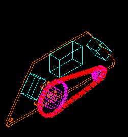
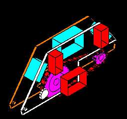
Here is now the first set of chains and gears added. The big gear mounts to the motor and the smaller one will be connected to the drive wheel.
The second plate has been added. It doesn't look like it but this plate (white) sandwiches the gear and chains between the plates. This plate is also drilled and tapped to mount to the light blue blocks.
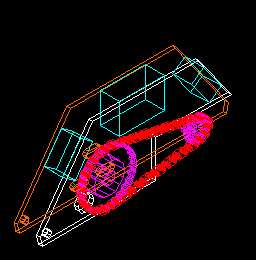
We have now added our second blocks (red)
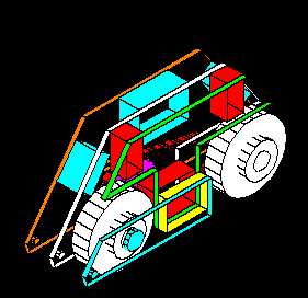
Here are some renderings of the same assembly which may be easier to see.
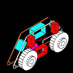
We have now added the two 4 inch diameter drive wheels. I have like a bigger drive wheel but have found problems fitting everything in. Anything smaller and I would be more worried about the tires ability to travel over bumps and uneven surfaces. The 4 inch wheels also allow the wheels to be further apart for more stability in 2 legged mode. (I hope)
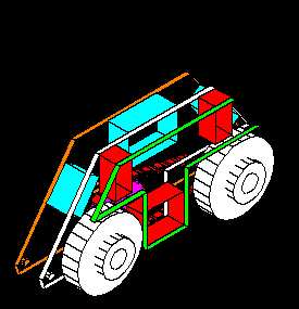
The green plate has been mounted to the red blocks. The main function of this plate is the other half of the mounting point for he ankle pivot point.
The yellow block has been added
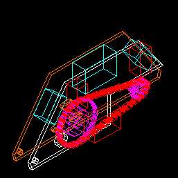
The blue plate is screwed to the yellow plate and now captures the front wheel. The rear wheel will be attached to it's own plate that is designed to allow adjusting to get the chain tight.
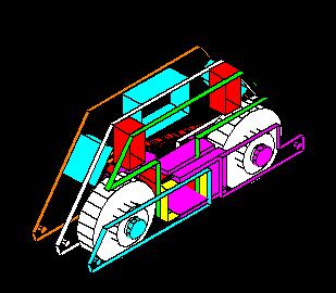
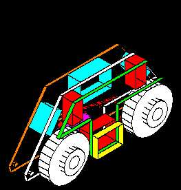
The next assembly (purple) captures the rear drive wheel and the smaller gear. This assembly is adjustable to keep the chain tight. This area took quite a few tries to design due to the limited space in the feet area. If you were looking at driving only one wheel then this area can be simplified a lot.
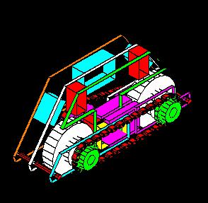
And now we add a second set of gears and chains to the system to drive both wheels. Adding a second set of gears and chain tensioning system does add complexity to the system. It does increase the areas where failure can occur but I think the benefits outweigh the negatives. If this drive chain fails in some way the rear wheel will still be driven so R2 will not be completely stranded.
Any thoughts and comments on my design would be appreciated. If there are any glaring faults you can see with my design please contact me.