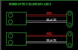
Start with 2 fiberoptics led units, a switch and wire. Wires should be two different colours but this is not necessary. Test the LED units with a 9 volt battery to make sure they are working.
R2D2 Dome Wiring 101
September 27 2002
Start with 2 fiberoptics led units, a switch and wire. Wires should be two different colours but this is not necessary. Test the LED units with a 9 volt battery to make sure they are working.
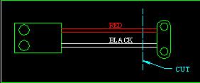
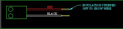
Cut the 9VDC connector off the unit and strip the wires so you have about 3/8" of bare wire.

Cut a couple of lengths of wire to connect to the LED units. I recommend 18 inches long. Later on this can be cut shorter. It is better to start long than to find out later on that your wires are too short. These wires will also be stripped on both ends. You will then connect the wires together. Normally soldering does this. After soldering the joint is covered with electrical tape.
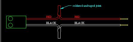
After soldering and taping the wire joints repeat with the second LED unit

Join the wires from the LED units and test to make sure both work by applying power with a 9 volt battery. Match up the wire colours. If the LEDs do not light up the battery terminals may be switched around. If one lights up and the other does not then the wires are switched around on one unit.
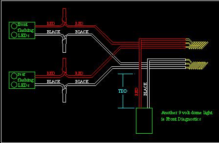
If there are any other 9 volt item in the dome that you want turned on with the flashing LEDs you should wire it in now. Once this item is wired in it should be tested again to make sure everything works. If things do not light up either the battery is the wrong way or the wires have been mixed up. By now you should get an idea of where everything goes in the dome. Any new additions make sure you have long enough wires so things can be mounted in their desired positions later on.

Next attach these wire ends to the DC to DC inverter (12VDC to 9VDC). If you have a voltage meter, check the output of the inverted to make sure it is pumping out 9VDC. This also checks to make sure the wiring into the Inverter is correct. Before soldering the connections apply 12 VDC to the input of the inverter and make sure the LEDs light up. If they do not then the wires coming out of the inverter are switched. Once you are satisfied that your wired are all ok then solder the 9VDC wires of the inverter to the LEDs and cover with electrical tape.
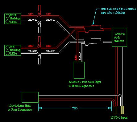
You can now add other 12VDC dome items to the wiring. This can be other lights or motors. Note we will be adding a switch later on so make sure it is items that you want on only when the two flashing LEDs are on. Before soldering test the entire circuit with a 12 V battery.

Now we add a switch to turn all the stuff on and off. Most switches use a 1/4" spade connector (not space as seen in the diagram above) Spade connectors can be purchased at electronic and automotive stores. Other switches may have 3/8" spade connectors, soldering tabs or screws. Our example will use the Spade connectors. The length of your wires will depend on where you are going to place your switch. If your switch is in the lower skirt then make sure the wires are long enough to reach this location.
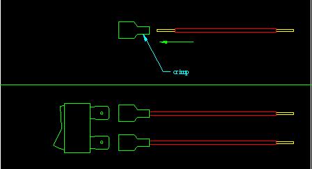
The wire is inserted into the space connector and then crimped. The wire should be in tight and should not be able to be pulled out. Repeat for the second wire and then insert into the switch.
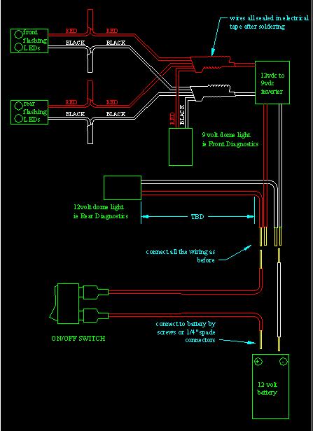
This is the location of the switch in the wiring harness. The switch acts to break the current flow to the LEDs and lights. There is some debate on the placement of the switch on the positive or negative side of the battery but I prefer the positive side.

Most 12VDC 7AH gel cell batteries has a 1/4" spade connector. You will have to crimp on a couple of these connectors to the ends of the wires. To keep things straight you have to remember that the black wire goes to the negative terminal. To play it safe it is advised that you put a piece of tape at the spade connectors and mark a '+' and a '-' on the tape so you are not confused at which side goes to which battery terminal.

We now simplify the wiring diagram to represent what most wiring diagrams look like.

A few rearranging of the wires to make is easier to read and we have eliminated the colours.

Now we have rearranged the parts to get the diagram as compact as possible. If there are any questions just email me ask@interlog.com