jvn26.jpg
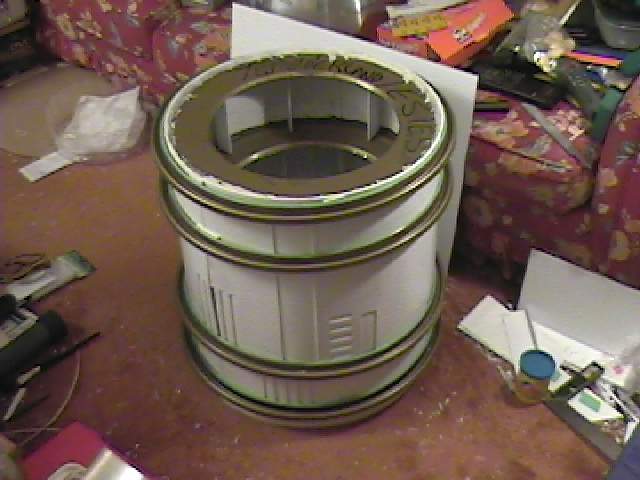
Jan 5 2001 - Here is my body so far. The skin was laid out on 0.125"
Styrene sheet and
the holes cut out. This weakened certain areas so I
added thinner styrene sheets to the
cut out areas. I tried to roll the
skin but it did not want to obey. I got these steel lids from
work.
They are 16Ga steel. I cut out the inner circle to use inside the skins. It
worked
out that I also got the outer rings, which I needed to keep the
body round as I added the
inner rings. There are 4 inner rings that
were glued in. This was done to avoid having
to put screws through the
skin to attach to a frame.

jvn27.jpg
Here is a close up of the inner rings. The writing on the top is not mine
but was on the
lid when I got it. The lid had several ridges pressed in
which made it relatively
strong. The holes in the rings were cut out after
all the rings were glued in. The styrene
spacers were added for the next
step. You can see slits in the inside of the ring edge.
This was done so I
could bend this back onto itself to make a stronger lip.

jvn28.jpg
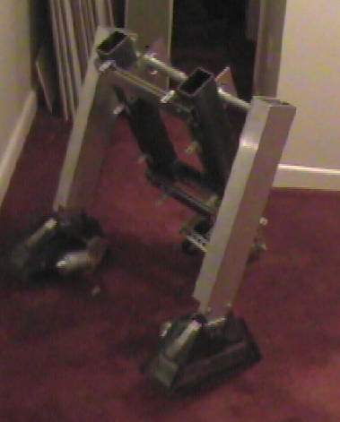
Here are my legs and feet moving along.

jvn29.jpg
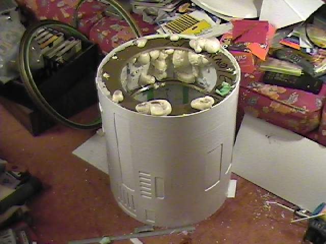
As you saw before in the body shot I added styrene inner bulkheads and
closed them
off. I then injected them with foam. The purpose of this
was to try and produce a strong
inner body and give the skin something
to hold onto instead of only the rings.

jvn30.jpg
Looking down into the body you can see the excess foam oozing out. To me
this is a
good sight as this was supposed to mean that the inner
cavities were full. I found out
later on that this was not
true.

jvn31.jpg
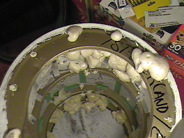
Foam everywhere. Do not touch this stuff as it sticks to everything. It
is best to wait
until it is dry before attempting to remove the excess
foam.
jvn32.jpg
To inspect the insides of the bulkheads I drilled holes into the
first ring and looked in.
It turns out that most of them were empty. I
think it was the brand I was using.
Another brand I used filled the
bulkheads very well.

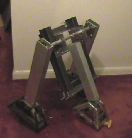
r212.jpg
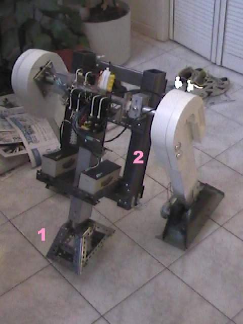
The frame so far. The frame has not been pinned
yet so everything
can fall apart any second. The yellow screwdriver
below the from
middle foot keep the thing from falling. The middle foot
is also
screwed to the frame. Later on I will change it so it can
travel
up and down.

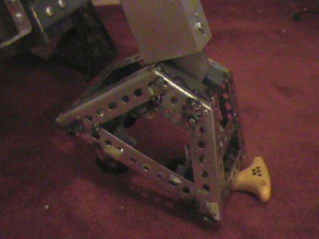
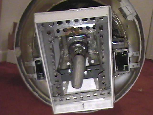
r213.jpg
Close up of the foot. There are 3 casters in
the middle foot. Unfortunately the two back
ones are too close to the
center and the foot tends to tip when going backwards. I will
have to
reposition these.

r214.jpg
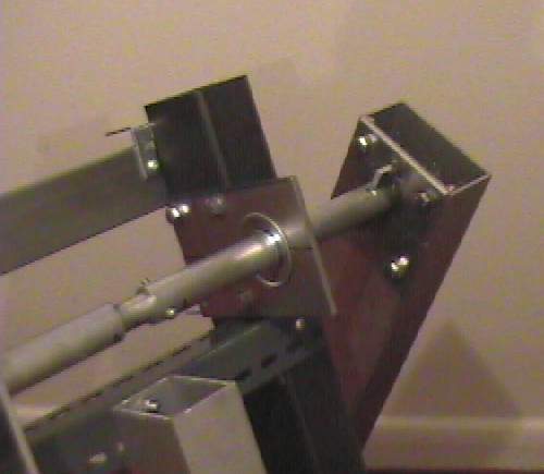
Close up of the frame and shoulder. So far
nothing keeps the bar in position
side to side and at the proper
angle.

r215.jpg
Rear shot of the frame.

r216.jpg
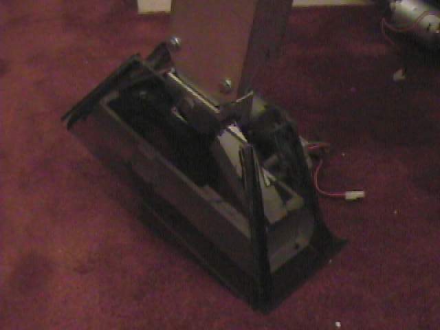
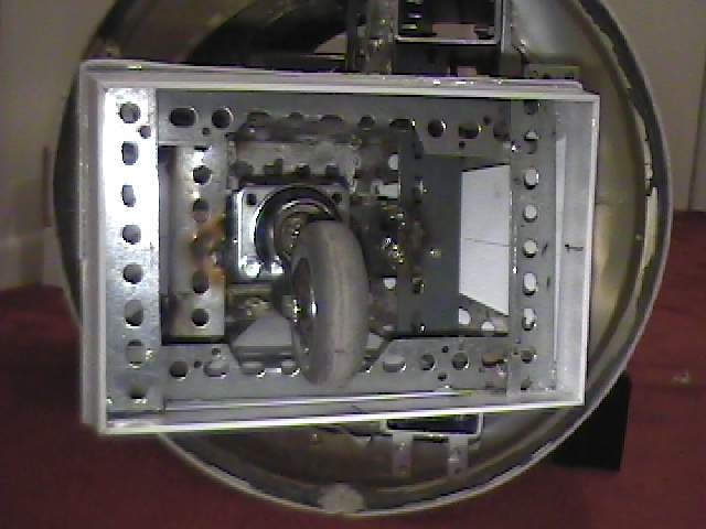
Close up of the foot. I tried to install a
caster inside so that I would not have to pin
the ankle but I haven't
been able to solve it for now so I will have to pin the ankle for now.

r217.jpg
MARCH
2001
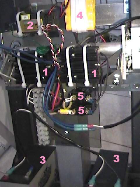
Here is a close up of my electronics board. Running out of
time I had to quickly
mount everything inside R2. It is actually very
convenient to have all the electronics
on a removable board. The board
is a Lexan sheet that is mounted to my middle leg.
No 1 are the two
speed controllers for my motors.
No 2 is the RC receiver.
No 3
are the two 12VDC 7AH gel cell batteries.
No 4 is the batteries for the
receiver.
No 5 are 7A fuses for the batteries.
Initially I had
one for each battery but later
changed it to one for the 24VDC
motors.

r218.jpg
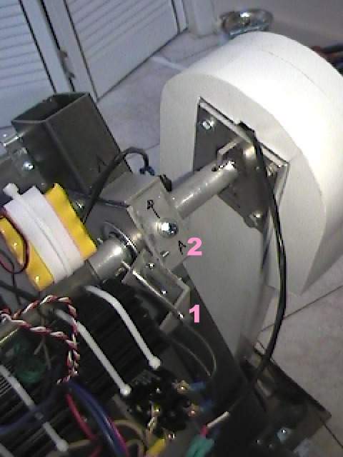
Here is a closeup of the shoulder area. I have
a 1" dia aluminum rod
connecting the left and right side of the legs.
Again because of a deadline
I had to pin the legs in position. In
location No 1 I first installed brass
rods to hold the legs in the
correct position for 3 legged mode held by
these small brackets. My
first attempts sheared these as if they were
toothpicks. I replaced
these with steel bolts. I also added a second pin
at location No
2supported by a section of aluminum square tubing.

r219.jpg
A shot of the frame as it rolled around. No 1
is my middle foot made out
of shelving angle welded together. I first
cut and riveted the parts together
to get the desired dimensions. I
then had the parts tack welded for strength.
No 2 is my steel square
tubing frame. The main vertical parts are made of
2x4s while the two
main horizontal bars are 1x2 square tubing.

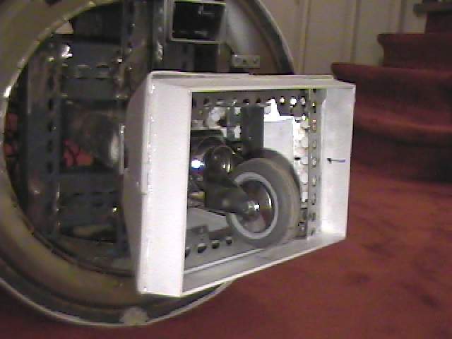
jvn01.jpg
Here is a picture of my new 3" caster in my
middle foot. I found that on my R2
the 3 smaller casters had problems
going over certain bumps. I also noticed
some damage to two of the
wheels after only a few days of running.

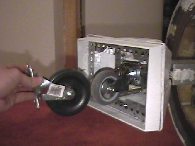
jvn02.jpg
Another view showing the swing of my 3" caster.

jvn03.jpg
Edge view showing the gap from the wheel to the skirt.

jvn04.jpg
Here is a 4" caster that I wanted to put in the middle foot.
I
only found out later that it was too big.
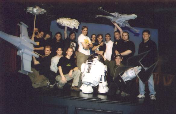
Here is a picture of the crew who were involved in the stage show. I am the
photographer so
that is why I am not in the picture. I built the X-Wings and
Tie Interceptors. The guy holding
the Falcon (Derek) built it. So with These
ships and R2 life was a bit busy. A very fun time

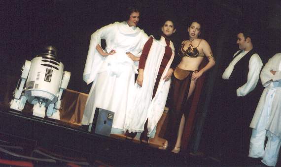
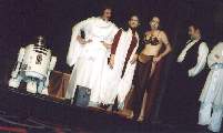
Here is R2 in stage. The sketch was called "The Empire Strikes Back To The
Future". It is a
cheesy time travel episode where young Luke falls for Queen
Amadela. From left to right, R2D2,
Princess Leia (Star Wars - A New Hope),
Princess Leia (The Empire Strikes Back), Princess Leia
(Return of The Jedi),
Han Solo (Checking out the Princess) and part of Obi-Wan
If you want to build your own R2 go here --http://groups.yahoo.com/group/r2builders
or here --http://movies.groups.yahoo.com/group/astromechs
for an R7 go here --http://movies.groups.yahoo.com/group/r7droidbuilders
Email me ask@interlog.com