The Construction of my R2D2
I have again modifed my R2 building section.(June 2002)
It was getting a bit long for one page and I have split it up to allow it to load up a bit faster.
If you are serious about starting your own R2 I say go to the R2 yahoogroups and join up.
Here you will find parts, blueprints and almost every idea on how to build your own R2.
The members in this group are very helpful. Here I started the body. Used rough drawings
from the R2 club. I redrew these in Autocad and increased the size for my 18.5"OD
Dome. I printed this out in full size then used this as a template on styrene.
HISTORY - Added April 19 2002
I have always wanted to build an R2-D2 but have never tried anything this big. I have
build quite a few model kits and have helped building sets and props for a student theatre
show I volunteer for. One rather complex prop I scratch built was a 1:10 scale F18 Fighter plane.
After finishing this I thought it wasn't as hard as I thought. R2-D2 was my next goal. Lack of
real information slowed the project. What kick started the project was a request to have a
full size R2-D2 for the student theatre show I volunteer for. Although a project that would
take quite a bit of time I decided to give it a shot. At that time I had about 16 months to get R2
finished.
It took some very late nights and a lot of help from the R2 Builders group but I got R2 rolling
for his stage debut. Without the deadline for the stage show I don't think I would be where I am today.
Although I did get R2 running I was missing a few details and I didn't have the dome running or any
lights yet. These would come later.
Now I am not saying that you have to be a master modeller to build an R2. There are quite a few
members of the group who have built an R2 and have been very surprised at what they can actually do.
One didn't think he had any skills at all and his static R2 turned out great. I am not very good in
electronics so if I have questions on how to wire things up I would as the group and someone would
come up with an answer to my question.
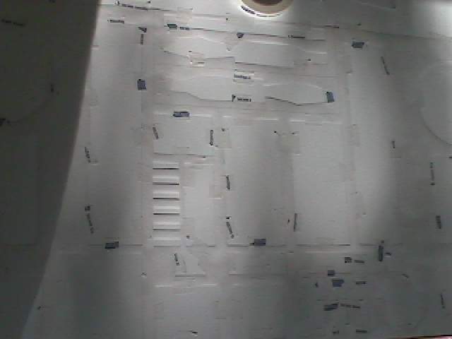
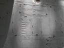
Here is a picture of all the panels cut out on the paper. I cut through the paper with an
exacto knife while at the same time scoring the plastic. Later on I will use a scriber to
make the panel lines deeper. The scriber I bought at a hardware store that is used to cut
acrylic sheets or vinyl floor tiles. It cost only $3. Dedicated hobby stores have them but
they are a lot more expensive. They are used to mainly scribe the panel lines on aircraft models.
r203.jpg
Close up of the panels. After cutting out the paper I taped the opening to prevent the paper
from shifting. In hindsight I should have scribed the lines when the styrene sheet was flat.
I was worried that if I scribed them now then the longer lines would make it harder to achieve
a perfect circle when I rolled the styrene sheet. After rolling the sheet and adding two more
layers I found scribing the lines time consuming.
Nov 26 2000
It has been a while since the last update so here goes. A lot of the time has been spent on the
planning. The first body done above was too short. I had to redo the scribing and laying out
of panels. This time I did a lot more scribing before bending the styrene into tube shape. This is
almost ready to make into a tube shape.
I also found out that the RC speed controllers I had would not work with the motors I purchased.
Anyone want to buy a burnt speed controller? I finally opted to purchase solid state speed controllers.
A bit pricey but these are supposed to give me the fine control I need. I also purchased a 6 channel ground
remote control unit.
r205.jpg
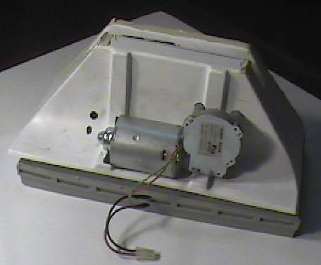
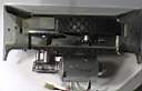
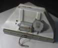
Here is the first picture of the feet so far. I purchased a feet kit from a egroup member.
With the plans in the files section now, if I started my R2 now then I would scratch build them
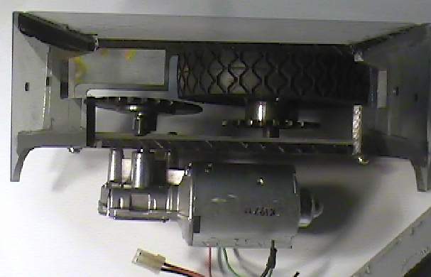
This was just the outside so I still had to work on the internals. At the bottom is the motor
I purchased. The rubber wheel is 6" dia I purchased from a hardware store. On it I had
welded a short length of tube to a gear. I plan to run the wheel by chain. To the left of
the rubber wheel is the second gear hooked up to the motor. It is not lined up because
I placed the gear in position for the picture. The feet frame is 1/4" Lexan. The wheels,
gear and motor are mounted to a 2"x3" aluminum tube with sections cut out for the wheels etc.
r206.jpg
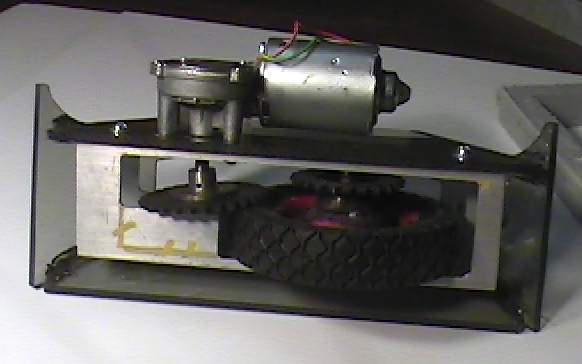
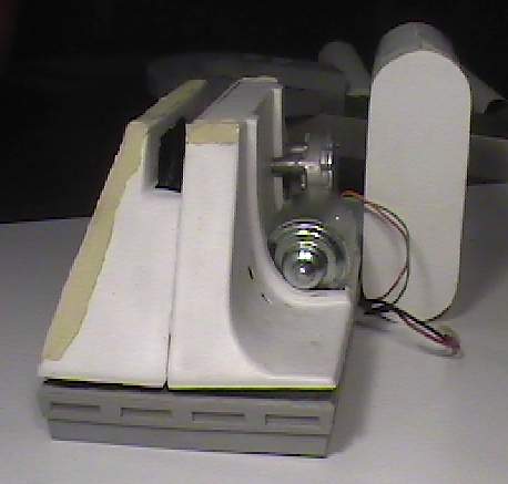
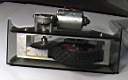
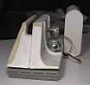
Another view with a clearer picture of the aluminum square tube the wheel is mounted to.
Eventually I had to cut out the section of aluminum marked out in yellow. This was the only
way I could get the drive gear in.
r207.jpg
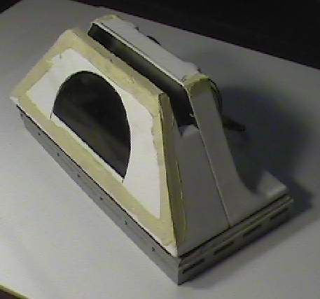
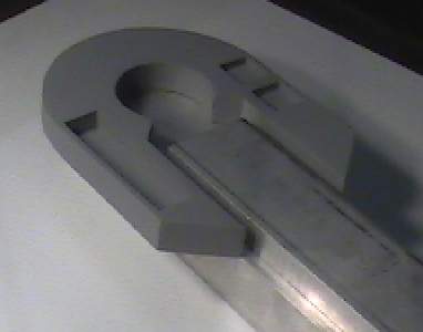
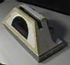
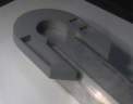
Here is what the purchased foot looks like. The edges were soft in detail so
I added automotive putty to sharpen them up. The bottom skirt is too thick
and heavy. I will scratch build a new one.
r208.jpg
Here is the foot with the cover on and where the motor is located.
r209.jpg
Here is a front view with the battery box which will cover the motor.
r210.jpg
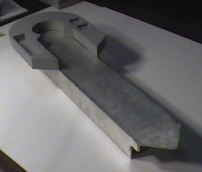
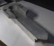
Here is the shoulder I made sitting on the 2x4 aluminum tube.
On the 2x4 is the 2x3 tube I cut in half.
r211.jpg
Here is the bottom of the 2x4 angled to be mounted to the foot.
If you want to build your own R2 go here --http://groups.yahoo.com/group/r2builders
or here --http://movies.groups.yahoo.com/group/astromechs
for an R7 go here --http://movies.groups.yahoo.com/group/r7droidbuilders
Email me ask@interlog.com